Wiring Diagram
D4155 110-volt Magnetic Switch Wiring Diagram:
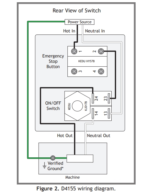
*The machine MUST be connected to a verified ground. In the event of certain malfunctions or breakdowns, grounding reduces the risk of electric shock by providing a path of least resistance for electric current.
Installation
This switch is intended to be connected to stranded wire with insulated crimp-type wire terminals. The emergency stop button requires ring wire terminals.
The ON/OFF switch requires female quickdisconnect wire terminals. All crimps must be “pull-checked” to ensure that wires re securely crimped and will not fall out with moderate tension or when exposed to normal machine vibration.