What color are the hall sensor wires?
Hall sensor wires typically follow a standard color code, but this can vary depending on the manufacturer or application. Commonly, the wires are ( hall sensor wiring diagram ) :
- Red: Power supply (+5V)
- Black: Ground
- Yellow, Green, and Blue: Signal wires for the three phases (A, B, and C)
- method works for vehicles that are compatible with magnet-based TPMS activation.
Hall effect sensor wiring diagram
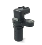
How many wires does a hall sensor have?
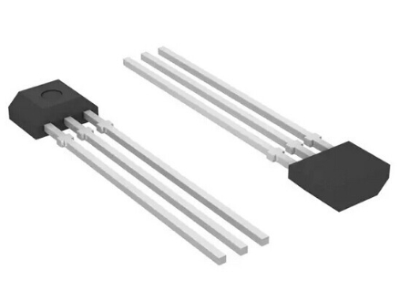
A hall switch sensor typically has three wires, which correspond to:
- Power supply: Usually connected to a positive voltage source (e.g., 5V or 12V).
- Ground: Connected to the negative side or ground of the circuit.
- Signal output: Transmits the sensor’s output signal to the controller or electronic system.
Some Hall sensors used in more complex applications, like crankshaft position sensor hall effect, may have additional wires for multiple signal outputs or diagnostics.
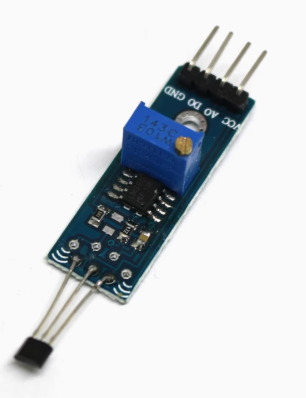
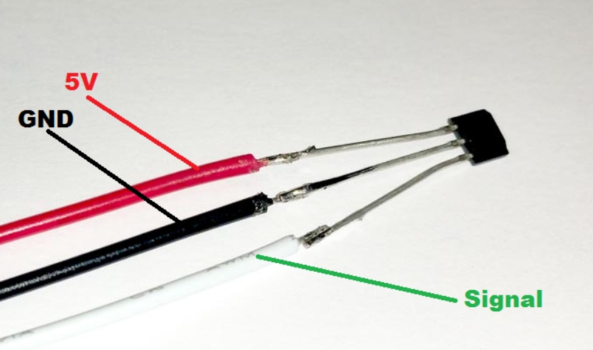
How to identify hall sensor wires?
Identifying Hall sensor wires can be straightforward if you follow these steps:
- Check the Documentation: Refer to the datasheet or user manual for the Hall sensor, as it often provides the wire color coding and pinout information.
- Standard Color Coding: Many Hall sensors use standard colors:
- Red: Power supply (+5V or +12V)
- Black: Ground (negative terminal)
- Signal: Usually a different color like green, yellow, or blue for the output.
- Use a Multimeter:
- Set your multimeter to measure voltage.
- Connect the sensor wires to the appropriate power source (e.g., red to positive, black to ground).
- Test the remaining wire(s) while moving the sensor near a magnetic field to detect a voltage change, confirming it’s the signal wire.
- Visual Inspection: Look for labels or markings on the Hall sensor’s housing or wire connectors. Some sensors come with markings to indicate power, ground, and signal.
What is the white wire for on a hall sensor?
The white wire on a Hall sensor is often used as a signal wire for specific functions, such as speed sensing or additional data output. Its exact purpose can vary depending on the application or device. For example, in some systems, the white wire might be dedicated to a speed sensor or a secondary signal output.