Knowing Top 10 DO Sensor Installation Mistakes and How to Avoid Them are important to avoid inaccurate water quality data in industries from wastewater treatment to aquaculture. Even advanced sensors fail without proper setup. This pillar content synthesizes expertise from YSI, Hach, and Emerson to reveal the top 10 DO sensor installation errors and their solutions, ensuring reliable measurements, extended sensor lifespan, and reduced maintenance costs.
1. Incorrect Sensor Orientation
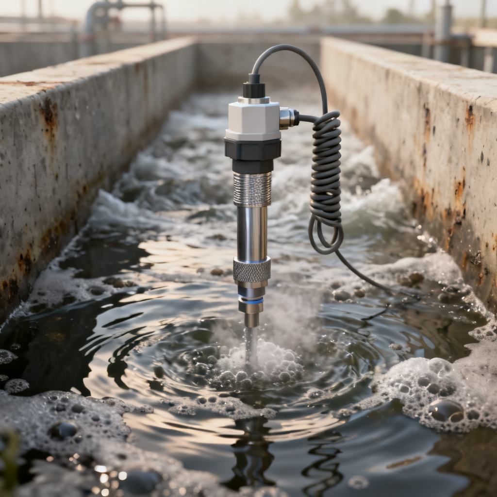
DO sensor installation often begins with orientation errors. Many installers position sensors horizontally or at an angle that traps air bubbles, leading to erratic readings because bubbles interfere with oxygen diffusion across the membrane.
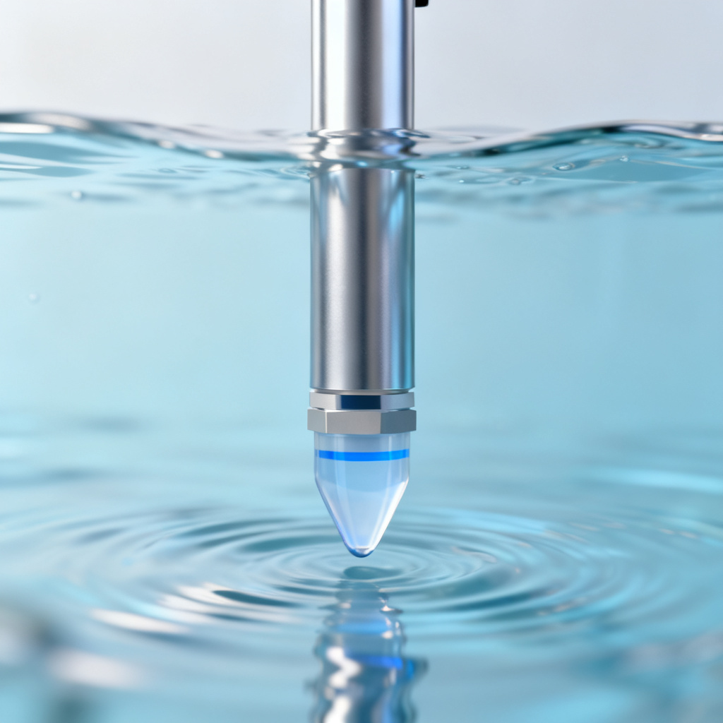
How to Avoid: Always install the sensor vertically with the membrane facing downward. YSI recommends a downward angle of at least 10–15 degrees for optical DO sensors to prevent bubble accumulation. In high-flow applications, use a flow guard or shroud to stabilize the sensor orientation.
2. Ignoring Flow Requirements
Electrochemical (Clark-type) DO sensors require a minimum flow rate to consume oxygen at the cathode and maintain a steady reading. Stagnant water causes oxygen depletion at the membrane, resulting in falsely low readings.
How to Avoid: Ensure a minimum flow rate of 0.3 m/s (1 ft/s) for polarographic sensors, as specified by Hach. For optical sensors, flow is less critical but still recommended. Use a submersible pump or install the sensor in a bypass line with a flow meter. In low-flow environments, choose optical DO sensors that are less flow-dependent.
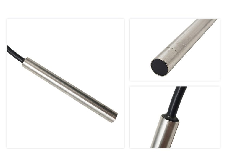
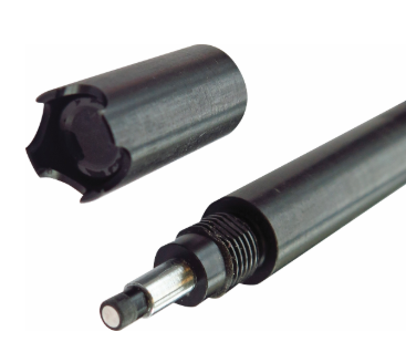
3. Improper Cable and Connector Management
Exposed connectors, cable strain, or moisture ingress at the junction cause signal drift or complete sensor failure. Many installers pull cables taut or allow them to drag across sharp edges.
How to Avoid: Use a strain relief system to protect the cable and connector. Emerson advises securing cables with UV-resistant zip ties and avoiding tight bends (minimum bend radius: 10x cable diameter). Seal all connectors with dielectric grease or waterproof caps. For submersible installations, ensure the cable gland is properly tightened and the connector is rated for IP68.
4. Inadequate Calibration Before Installation
Sensors are often installed without a baseline calibration, leading to offset errors from the start. This is common when sensors are shipped dry or stored for long periods.
How to Avoid: Perform a two-point calibration (0% and 100% saturation) in a controlled environment before installation. Use the saturated air method for 100% calibration, as recommended by YSI. For zero-point calibration, use a sodium sulfite solution or nitrogen purge. Record the calibration slope and offset; if they deviate by more than 10% from factory specs, clean or replace the sensor.
5. Neglecting Temperature Compensation
DO solubility is highly temperature-dependent. Installing a sensor without enabling or verifying temperature compensation results in erroneous readings, especially in fluctuating temperature environments like seasonal ponds or industrial processes.
How to Avoid: Ensure your sensor has an integrated temperature probe and the controller is set to automatic temperature compensation (ATC). Hach emphasizes the temperature reading must be within ±0.2°C of the actual water temperature. For manual compensation, use a separate thermometer and update the value regularly.
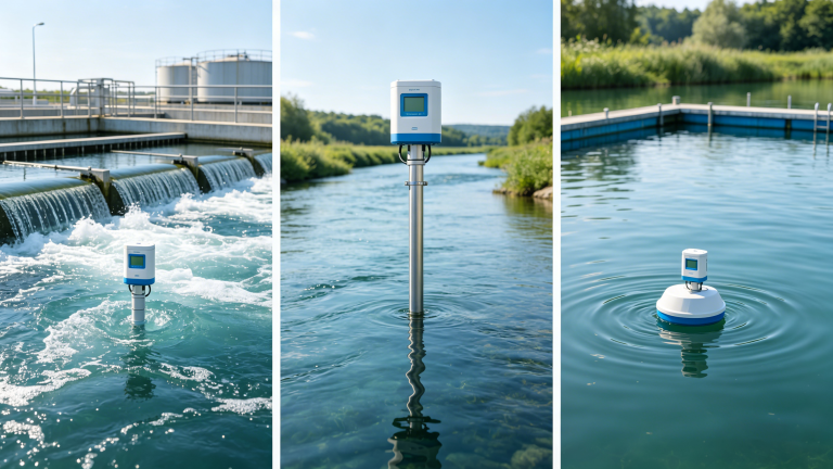
6. Placement in Dead Zones or Stratified Water
Installing DO sensors in areas with poor water mixing—such as tank corners, near sludge blankets, or at the bottom of stratified lakes—yields readings that are not representative of the overall system.
How to Avoid: Place sensors in well-mixed zones with consistent flow. For wastewater treatment, install in the aerobic zone or aeration basin, away from inlets and outlets. In natural waters, use a vertical profiler or install at multiple depths. Emerson recommends a minimum distance of 1 meter from any wall or obstruction.
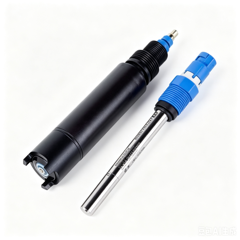
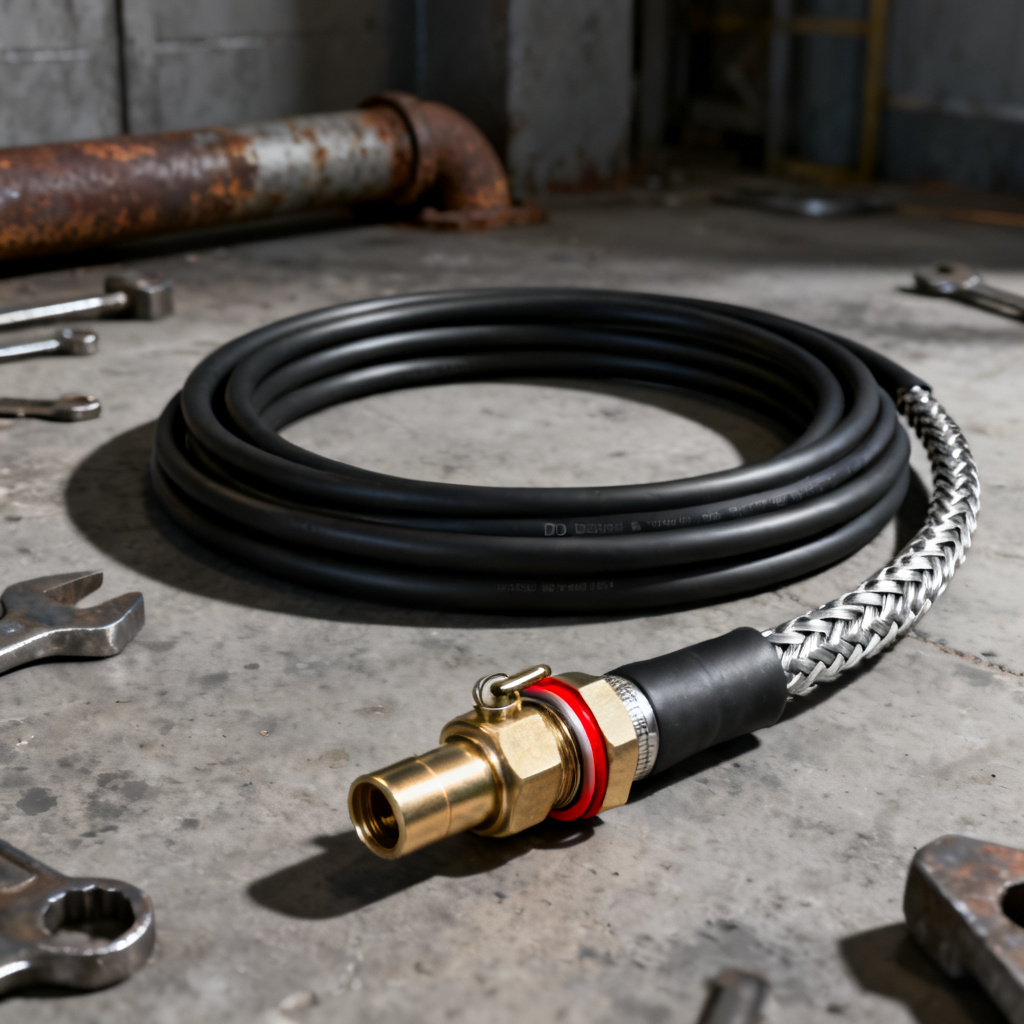
7. Using Incorrect Mounting Hardware
Standard metal brackets or PVC pipes can corrode, leach chemicals, or cause galvanic reactions. Some installers use rigid mounts that don’t accommodate sensor removal for cleaning.
How to Avoid: Use mounting hardware made from stainless steel (316 grade), marine-grade PVC, or HDPE. For chemical environments, Hach suggests polypropylene or PTFE brackets. Ensure the mount allows easy retraction for maintenance—consider a quick-release clamp or telescopic pole. Avoid aluminum or brass, which corrode in saltwater or chlorinated water.
8. Skipping Routine Cleaning and Maintenance
Biofouling (algae, bacteria, or sediment) on the membrane or optical window is the leading cause of drift in DO sensors. Many installers assume a “set-and-forget” approach, leading to data degradation within days.
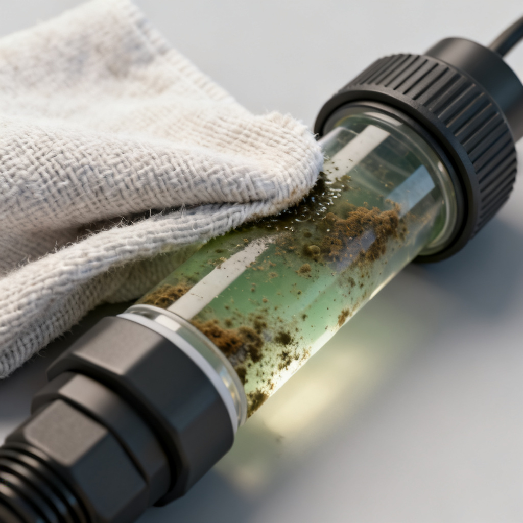
How to Avoid: Implement a cleaning schedule based on water conditions. For clean water, clean weekly; for wastewater, clean daily or after each batch. Use a soft cloth and mild detergent for optical sensors, or a fine brush for polarographic sensors. YSI recommends a protective guard or wiper system for continuous submersion. Always rinse with deionized water after cleaning.
9. Ignoring Pressure and Depth Effects
DO sensors calibrated at sea level read incorrectly at high altitudes or deep depths because atmospheric pressure affects oxygen solubility. Submersible sensors may also be damaged by excessive hydrostatic pressure.
How to Avoid: For atmospheric pressure compensation, use a barometric pressure sensor or manually input local pressure (in kPa or mmHg). Hach notes that for every 1000 feet above sea level, DO saturation decreases by about 2%. For deep installations (over 10 meters), use a pressure-rated sensor (e.g., up to 30 psi) and calibrate at actual depth.
10. Overlooking Electrical Interference
Running DO sensor cables parallel to high-voltage power lines, motors, or variable frequency drives (VFDs) introduces electromagnetic interference (EMI), causing noisy or unstable signals.
How to Avoid: Route sensor cables in separate conduits from power cables. Use shielded twisted-pair cables (e.g., Belden 8723) and ground the shield at one end only (typically at the controller). Emerson advises keeping a minimum separation of 30 cm (12 inches) from any AC power source. For critical installations, use a signal isolator or Faraday cage.
DO Sensor Installation: Optical vs. Electrochemical
| Parameter | Optical DO Sensor Installation | Electrochemical DO Sensor Installation |
|---|---|---|
| Flow dependency | Low – minimal flow required | High – minimum 0.3 m/s needed |
| Calibration frequency | Less frequent (monthly) | More frequent (weekly) |
| Maintenance | Clean optical window only | Replace membrane and electrolyte |
| Best for | Low-flow or clean water applications | High-flow or wastewater environments |
Frequently Asked Questions About DO Sensor Installation
What is the most common DO sensor installation mistake?
How often should I calibrate my DO sensor after installation?
Can I install a DO sensor in stagnant water?
Key DO Sensor Installation Terminology
- Polarographic sensor: An electrochemical DO sensor that consumes oxygen during measurement, requiring flow.
- Optical sensor: A luminescence-based DO sensor that does not consume oxygen, making it less flow-dependent.
- Biofouling: The accumulation of microorganisms on sensor surfaces, causing measurement drift.
- Galvanic isolation: Electrical separation between sensor and controller to prevent interference.
By avoiding these 10 DO sensor installation mistakes, you will achieve accurate, consistent readings for process control, regulatory compliance, and environmental monitoring. For custom sensor solutions or expert support, contact our team—we design high-performance DO sensors tailored to your application.
💡 Frequently Asked Questions (FAQ)
1. What is the most common mistake in DO sensor installation?
The most common mistake is incorrect placement, such as installing the DO sensor in a “dead zone” with poor water flow or too close to aerators. This leads to stagnant readings or artificial air bubbles trapped on the membrane, causing inaccurate dissolved oxygen data.
2. What is the ideal mounting angle for a dissolved oxygen probe?
A dissolved oxygen probe should typically be installed at a 15 to 45-degree angle rather than perfectly vertical or horizontal. This tilted angle prevents air bubbles from accumulating on the sensor membrane and ensures continuous flow across the optical cap or electrochemical tip.
3. How does improper sensor installation affect calibration?
If a DO sensor is installed in an unstable environment (e.g., severe vibration or rapid temperature fluctuations), it will experience signal drift. This forces frequent recalibrations and significantly shortens the lifespan of the sensor’s optical cap or electrolyte solution.
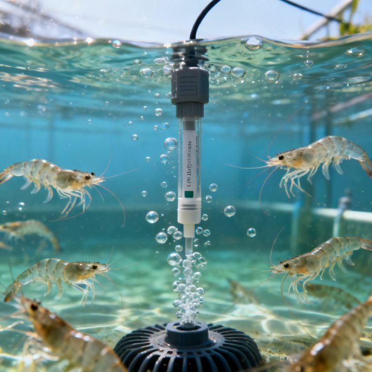
4. Can I install a DO sensor directly in a wastewater aeration tank?
Yes, but it must be installed using a proper protective mounting bracket or immersion sleeve. Avoid placing it directly beneath chemical dosing points or in paths where heavy solid waste can physically impact and damage the sensor membrane.
5. How often should an installed DO sensor be checked for cleaning?
In high-fouling environments like wastewater or aquaculture, the installation setup should allow for easy access to clean the sensor every 1 to 2 weeks. Automated spray cleaning systems or anti-fouling guards can be integrated during installation to reduce manual maintenance.