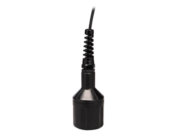
DO6440 Galvanic Dissolved Oxygen Sensor
Industrial-grade galvanic electrochemical DO probe with 4-20mA current loop output and Modbus 485 digital communication. Engineered for continuous online monitoring in wastewater treatment, commercial aquaculture, and industrial process water systems.
Introduction to the DO6440 Galvanic Dissolved Oxygen Sensor
The DO6440 galvanic dissolved oxygen sensor represents a robust, field-proven solution for continuous dissolved oxygen monitoring across demanding industrial and environmental applications. Unlike optical or luminescent DO sensors that require complex light-emitting components, this galvanic electrochemical device generates its own millivolt signal through a spontaneous redox reaction between its silver cathode and zinc wire anode — no external excitation power required for mV output models.
The DO6440 series encompasses multiple output configurations to match diverse instrumentation ecosystems: the DO6441 delivers standard 4-20mA current loop output (18–22 mA at 100% saturation), the DO6442 provides an alternative 4-20mA range (11–14 mA at 100% saturation), and the -MB variants (DO6441-MB, DO6442-MB) add full Modbus 485 digital communication for direct SCADA integration without signal converters.
Measurement Principle: How the Galvanic Electrochemical Cell Works
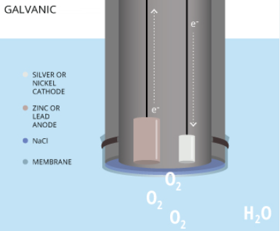
Understanding the internal operation of a galvanic dissolved oxygen sensor is essential for proper deployment and maintenance. The sensing element comprises four key components working in concert:
- Silver Cathode: Oxygen molecules diffusing through the membrane are reduced at the silver surface, consuming electrons.
- Zinc Wire Anode: Oxidizes spontaneously, releasing electrons that flow through the external circuit to the cathode.
- Sodium Chloride Electrolyte: Provides ionic conductivity between electrodes. A saturated NaCl solution fills the sensor cavity beneath the membrane.
- Oxygen-Permeable Membrane: Available in PTFE (faster response, ~5 minutes T90) or HDPE (higher output ~48±8 mV) formulations. This selective barrier allows O₂ diffusion while blocking water and ions.
The resulting current is directly proportional to the partial pressure of dissolved oxygen in the process fluid, following Faraday’s law of electrolysis. For the DO6441 4-20mA model, air-saturated output typically reads 18–22 mA; for the DO6442 variant, 11–14 mA under identical conditions. Zero-oxygen conditions produce less than 4.6 mA output.
Technical Specifications
| Parameter | Specification / Value |
|---|---|
| Measurement Principle | Galvanic Electrochemical Cell (self-powered) |
| Cathode Material | Silver (Ag) |
| Anode Material | Zinc Wire (Zn) |
| Electrolyte | Sodium Chloride Solution (NaCl) |
| Membrane Options | PTFE or HDPE (oxygen-permeable) |
| Output Signal (DO6441) | 4-20mA Current Loop (18–22 mA @ 100% sat.) |
| Output Signal (DO6442) | 4-20mA Current Loop (11–14 mA @ 100% sat.) |
| Digital Communication | Modbus 485 (DO6441-MB, DO6442-MB variants) |
| mV Output (DO6400 reference) | 36±8 mV (PTFE) / 48±8 mV (HDPE) @ 100% sat. |
| Zero Output | <1 mV (mV models) / <4.6 mA (mA models) |
| Temperature Range | 0 – 50°C (32 – 122°F) |
| Response Time (T90, PTFE) | ~5 minutes (100% → 0% O₂) |
| Minimum Flow Rate | 2 inches/second across membrane surface |
| Power Requirement | 24 VDC, minimum 150mA (4-20mA models only) |
| Housing Materials | PPO (top/bottom cap), POM (sensor body) |
| Wetted Materials | PPO, PTFE/HDPE membrane, PVC/polyurethane cable jacket |
| Cable Specification | 4-conductor, 24 AWG, copper/PVC, polyurethane outer jacket |
| Mounting Method | Submersion (recommended at slight angle to prevent bubble trapping) |
| Calibration Method | Single-point (air) or two-point (air + sodium sulfite zero) |
Industrial Applications
Wastewater Treatment Plants
Real-time dissolved oxygen monitoring for activated sludge aeration basins. The 4-20mA output integrates directly with PLC-based aeration control systems, reducing energy costs by maintaining optimal DO setpoints (typically 1.5–3.0 ppm).
Commercial Aquaculture
Continuous DO surveillance in intensive fish farming and shrimp hatcheries. Supports both freshwater and marine operations with salinity-compensated readings up to 40 ppt using built-in temperature compensation.
Industrial Process Water
Boiler feedwater deaeration verification, pharmaceutical water-for-injection (WFI) systems, food and beverage production lines, and cooling tower blowdown control where precise oxygen levels prevent corrosion and microbial growth.
Environmental Monitoring
River and lake water quality assessment stations, groundwater remediation sites, and stormwater retention basin monitoring where long-term unattended operation and minimal maintenance are priorities.
Installation & Wiring Guide
Electrical Connections for 4-20mA Models (DO6441, DO6442)
Standard 4-20mA Wiring Diagram
Red wire → DO Input + (cathode positive)
Black wire → DO Input − (anode negative)
White wire → Temperature input (for ATC-enabled meters)
Green wire → Temperature input (complementary)
Modbus 485 Wiring (DO6441-MB, DO6442-MB)
Digital Communication Wiring
Red wire → Power input (+7 to 30 VDC)
Black wire → Ground (GND)
White wire → Modbus 485 A(+) data line
Green wire → Modbus 485 B(−) data line
Mounting Recommendations
Submersion mounting is the recommended installation method for the DO6440 galvanic dissolved oxygen sensor. To prevent air bubbles from becoming trapped against the membrane surface — which produces falsely high DO readings — orient the sensor at a slight angle (approximately 5–15° from vertical). Ensure a minimum water flow velocity of 2 inches per second across the membrane face to maintain accurate diffusion equilibrium.
Calibration Procedure
Single-Point Air Calibration (Recommended for Most Applications)
- Ensure the sensor is properly connected to your meter, controller, or data acquisition system with a live display.
- Gently wipe the membrane surface with a soft, lint-free cloth to remove biofilm or debris if the sensor has been in service.
- Hold the sensor in still air, away from direct sunlight, and wait 3–5 minutes for temperature equilibration.
- Record the stable output value as your 100% saturation reference point (e.g., 36.0 mV for DO6400/T, or 12.0 mA for DO6442/T in air).
- Enter this value into your instrument’s calibration menu as the air-saturated endpoint.
For routine wastewater and aquaculture monitoring above 3 ppm, single-point air calibration combined with the assumed zero-point (<1 mV or 4.25 mA) provides excellent accuracy due to the sensor’s linear output characteristic.
Two-Point Calibration (Required for Measurements Below 2 ppm)
- Complete the single-point air calibration steps above.
- Prepare a zero-oxygen solution by dissolving 17 grams of sodium sulfite (Na₂SO₃) in 125 mL of deionized water.
- Immerse the sensor tip in the sodium sulfite solution and wait 5 minutes.
- Verify the reading drops below 2 mV (mV models) or below 5 mA (4-20mA models). Record this as the zero point.
Maintenance & Reconditioning
The DO6440 galvanic dissolved oxygen sensor requires periodic maintenance to maintain factory-specified accuracy. The sensor ships dry — you must install a fresh membrane and fill with electrolyte before first use. The following reconditioning procedure should be performed every 3–6 months depending on operating conditions:
- Disassembly: Unscrew the lower body from the upper body. Safely dispose of the spent electrolyte (sodium chloride solution). Ensure the large sealing o-ring remains seated in the bottom cap groove.
- Membrane Removal: Using the supplied membrane lock tool, unscrew the membrane lock from the lower body. Remove and discard the used membrane and its o-ring.
- Electrode Cleaning: Immerse the upper sensor body (cathode and anode exposed) in distilled white vinegar (3% acetic acid) for approximately 30 minutes. Alternatively, clean the silver cathode, zinc anode, and intervening plastic surfaces with a soft toothbrush and mild dishwashing detergent. Rinse thoroughly with clean water.
- Reassembly: Install a new o-ring into the membrane cavity (press fully to the bottom). Peel the protective backing from a new PTFE or HDPE membrane and place it over the cavity. Add the spacer, then screw in the membrane lock using the tool — keep the cap upright during tightening.
- Leak Test: Pour clean water into the lower body and inspect for leakage around the membrane perimeter. Replace if leaks are detected.
- Electrolyte Fill: Fill the bottom cap to the brim with fresh sodium chloride electrolyte solution.
- Final Assembly: Hold the sensor upright (cable pointing upward). Screw the bottom cap onto the upper body until alignment marks align. Do not overtighten — a small visible gap at the joint is normal and correct.
Critical Maintenance Notes
- Never mix bottom caps between sensors — each cap is factory-matched to its upper body to prevent leaking and measurement errors.
- Replace the large o-ring during every reconditioning cycle. Pre-lubricate before installation, but avoid getting lubricant on the membrane surface.
- For long-term storage: empty electrolyte, rinse with clean water, remove membrane and membrane o-ring, and store completely dry.
Need a Portable Alternative? Consider the DO-9100 Pen-Type DO Meter
If your application requires field spot-checking, mobile troubleshooting, or temporary deployment rather than fixed continuous monitoring, consider our DO-9100 Pen-Type Intelligent Portable Dissolved Oxygen Analyzer:
- Faster Delivery: Standard models ship within 7–14 days vs. 4–6 weeks for custom-configured industrial probes
- No Installation Required: Battery-operated handheld design — no wiring, no conduit, no panel cutout
- Lower Entry Cost: Ideal for small-scale aquaculture operators, educational labs, and field technicians who need reliable DO readings without capital expenditure on fixed instrumentation
- IP67 Waterproof: Fully submersible for dip-check readings in tanks, ponds, and raceways
- Automatic Temperature Compensation: Built-in ATC from 0–50°C covers all common aquaculture and environmental testing scenarios
Trade-off note: The portable DO-9100 uses polarographic technology optimized for intermittent use. For 24/7 continuous online monitoring in harsh chemical environments, the DO6440 galvanic electrochemical sensor remains the recommended choice due to its rugged PPO/POM construction and industry-standard 4-20mA/Modbus outputs.