The Polarographic Dissolved Oxygen Sensor Working Principle is based on the electrochemical reduction of oxygen at a noble metal cathode, a method first developed by Dr. Leland C. Clark in 1956. This technology remains the gold standard for accurate dissolved oxygen measurement in wastewater treatment, aquaculture, and bioprocessing.
1. Electrochemical Foundation of Polarographic Dissolved Oxygen Sensor Working Principle
1.1 The Clark Electrode Origin
The polarographic dissolved oxygen sensor working principle originates from the Clark electrode, invented in 1956. Clark separated the electrochemical cell from the sample using a gas-permeable membrane, solving electrode fouling and flow dependency.
1.2 Core Reduction Reaction
The polarographic dissolved oxygen sensor working principle relies on oxygen reduction at a platinum or gold cathode under a stable polarizing voltage of 0.6–0.8 V DC. The reaction consumes electrons and produces a current proportional to oxygen partial pressure:
- Cathode reaction: O₂ + 2H₂O + 4e⁻ → 4OH⁻
- Anode reaction: 4Ag + 4Cl⁻ → 4AgCl + 4e⁻
- Overall: O₂ + 2H₂O + 4Ag + 4Cl⁻ → 4OH⁻ + 4AgCl
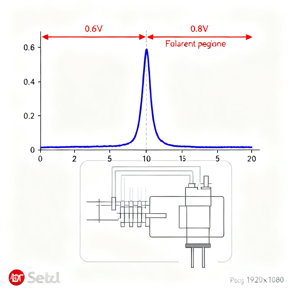
1.3 The Polarographic Plateau
In the polarographic dissolved oxygen sensor working principle, the polarographic plateau (0.6–0.8 V) ensures current is independent of voltage fluctuations, providing stable and linear oxygen measurement from 0–20 ppm.
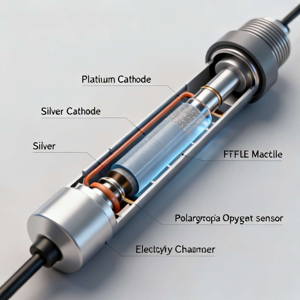
2. Anatomy of a Polarographic Dissolved Oxygen Sensor
2.1 Gas-Permeable Membrane
Made of PTFE or FEP, the membrane is hydrophobic and selectively permeable to oxygen. Thickness ranges from 12.5–50 µm, balancing response time (T90 < 60 seconds) with durability.
2.2 Cathode (Working Electrode)
Platinum or gold cathode with a precisely controlled surface area (0.1–1 mm²). The polarographic dissolved oxygen sensor working principle requires a polished cathode surface for uniform diffusion.
2.3 Anode (Counter/Reference Electrode)
Silver/silver chloride (Ag/AgCl) anode with 10–100 times larger surface area than the cathode. It provides a stable reference potential and completes the circuit.
2.4 Electrolyte Solution
Potassium chloride (KCl) solution (0.1–1 M), often buffered with KOH. The polarographic dissolved oxygen sensor working principle depends on ionic conductivity and hydroxide transport.
2.5 Housing and Temperature Compensation
Stainless steel or PEEK housing with an integrated thermistor or RTD for automatic temperature compensation (ATC), critical because oxygen diffusion changes 2–3% per °C.
3. Operational Mechanics of Polarographic Dissolved Oxygen Sensor Working Principle
3.1 Oxygen Diffusion Across the Membrane
Dissolved oxygen diffuses through the membrane driven by partial pressure gradient. Fick’s first law governs this diffusion-limited process, ensuring linearity.
3.2 Electrochemical Reduction at the Cathode
Oxygen is reduced at the cathode, consuming electrons. The current (I) is proportional to oxygen partial pressure (pO₂): I = k · pO₂, where k depends on membrane and cathode parameters.
3.3 Current Measurement and Signal Conditioning
The microampere current is converted to voltage via a transimpedance amplifier, then amplified, temperature-compensated, and digitized for 4–20 mA or Modbus output.
3.4 Polarization Time
Initial polarization takes 15 minutes to 2 hours. The polarographic dissolved oxygen sensor working principle requires steady-state diffusion before calibration.
4. Calibration for Accurate Polarographic Dissolved Oxygen Sensor Working Principle
4.1 Why Calibration Is Essential
The polarographic dissolved oxygen sensor working principle is relative; calibration corrects for membrane condition, electrolyte age, and barometric pressure variations.
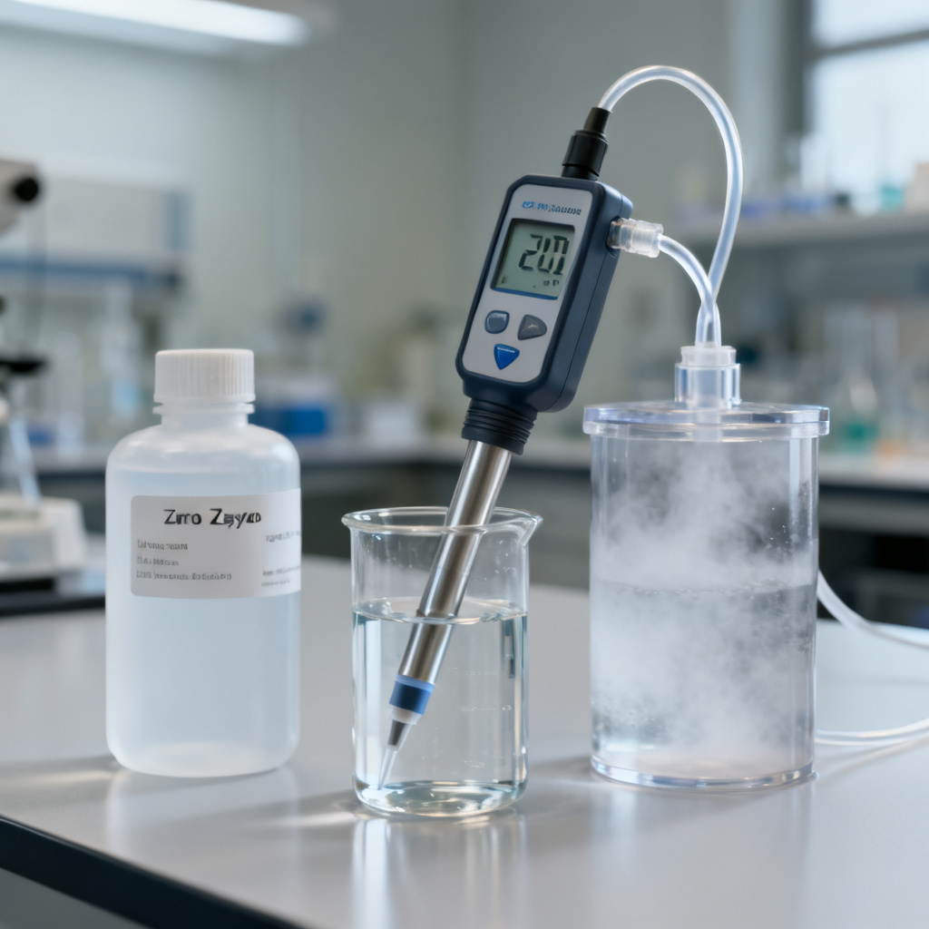
4.2 Two-Point Calibration Method
- Zero point: Sodium sulfite solution or nitrogen-purged water (0% saturation).
- Span point: Water-saturated air (100% saturation) with Henry’s Law correction.
4.3 Barometric Pressure and Salinity Corrections
Oxygen solubility decreases 0.1% per hPa pressure drop and 1–2% per ppt salinity increase. Modern transmitters apply automatic corrections.
4.4 Calibration Frequency
Clean water: every 1–2 weeks. Harsh environments (wastewater, bioreactors): every 2–7 days.
5. Performance Factors in Polarographic Dissolved Oxygen Sensor Working Principle
5.1 Response Time
T90: 30–90 seconds for standard membranes; 5–30 seconds for microelectrodes. Slow response indicates fouling or depleted electrolyte.
5.2 Flow Dependence
The polarographic dissolved oxygen sensor working principle consumes oxygen, requiring minimum flow velocity of 0.1–0.5 m/s to avoid depletion zone errors.
5.3 Interference and Cross-Sensitivity
- Chlorine: False elevated readings; use chlorine-resistant membranes.
- Hydrogen sulfide: Poisons silver anode; use gold-plated anodes.
- CO₂ and N₂: No interference.
5.4 Drift Over Time
1–5% per week drift from anode depletion, electrolyte evaporation, or biofouling. Regular maintenance is essential.
5.5 Temperature Effects
2–3% output change per °C. ATC using built-in thermistor is mandatory for the polarographic dissolved oxygen sensor working principle.
6. Applications of Polarographic Dissolved Oxygen Sensor Working Principle
6.1 Wastewater Treatment Plants
High accuracy at low DO (0–2 mg/L), robust construction, and compatibility with automatic cleaning systems.
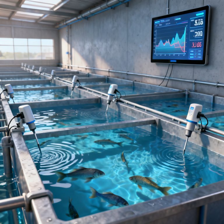
6.2 Aquaculture
Fast response to rapid DO changes in fish tanks and net pens; works in fresh and saltwater with salinity correction.
6.3 Bioprocessing and Fermentation
Sterilizable designs, excellent linearity, and compatibility with high-pressure bioreactors.
6.4 Environmental Monitoring
Sensitivity down to 0.01 mg/L, long-term stability for unattended deployment.
7. Maintenance Best Practices
7.1 Daily/Weekly Checks
Inspect membrane for tears, clean fouling, verify calibration with air-saturated water.
7.2 Monthly Maintenance
Replace electrolyte, clean cathode with micro-abrasive, inspect anode for silver chloride buildup.
7.3 Annual Maintenance
Replace membrane cap and O-rings; perform factory recalibration.
8. Troubleshooting Common Issues
| Symptom | Likely Cause | Solution |
|---|---|---|
| Reading too low | Fouled membrane, depleted electrolyte, low flow | Clean membrane, replace electrolyte, increase flow |
| Reading too high | Air bubble under membrane, chlorine interference | Remove bubble, use chlorine-resistant membrane |
| Slow response | Thick membrane, aging cathode, low temperature | Replace membrane, clean cathode, check ATC |
| Drift upward | Anode depletion, electrolyte contamination | Replace anode, refill electrolyte |
| Zero offset > 2% | Cathode contamination, membrane damage | Clean cathode, replace membrane cap |
| No current output | Broken cable, no polarizing voltage, dry electrolyte | Check wiring, verify voltage, refill electrolyte |
9. Comparison: Polarographic vs Other DO Sensor Technologies
| Feature | Polarographic (Clark) | Optical (Luminescent) | Galvanic |
|---|---|---|---|
| Working Principle | Electrochemical reduction | Fluorescence quenching | Spontaneous electrochemical cell |
| Requires Polarizing Voltage | Yes (0.6–0.8 V) | No | No |
| Oxygen Consumption | Yes (requires flow) | No | Yes |
| Response Time | 30–90 sec | 30–120 sec | 60–180 sec |
| Drift | Moderate (weekly calibration) | Low (monthly calibration) | High (daily calibration in harsh conditions) |
| Maintenance | Membrane, electrolyte, anode | Cap replacement every 1–2 years | Anode replacement, electrolyte refill |
| Flow Dependence | High | Negligible | Moderate |
| Accuracy at Low DO | Excellent (< 0.1 mg/L) | Good (0.1–0.2 mg/L) | Fair (0.2–0.5 mg/L) |
| Cost | Moderate | High | Low |
10. Future Trends in Polarographic Dissolved Oxygen Sensor Working Principle
10.1 Self-Cleaning Designs
Automatic cleaning jets, self-polishing cathodes, and long-life membrane caps extending maintenance intervals to 6–12 months.
10.2 Digital Communication
Modbus RTU, HART, Profibus for remote calibration and diagnostics; smart sensor chips storing calibration data.
10.3 Miniaturization
Microelectrode arrays (10 µm diameter cathodes) for microfluidic and medical applications.
FAQ: Polarographic Dissolved Oxygen Sensor Working Principle
What is the polarographic dissolved oxygen sensor working principle?
The polarographic dissolved oxygen sensor working principle involves electrochemical reduction of oxygen at a platinum cathode under a polarizing voltage, producing a current proportional to dissolved oxygen concentration.
How does temperature affect the polarographic dissolved oxygen sensor working principle?
Temperature changes oxygen diffusion and reaction rates by 2–3% per °C. Automatic temperature compensation (ATC) is essential for accurate measurement.
Why does the polarographic dissolved oxygen sensor working principle require flow?
The sensor consumes oxygen, creating a depletion zone. Minimum flow of 0.1–0.5 m/s ensures fresh sample reaches the membrane.
What is the difference between polarographic and optical DO sensors?
Polarographic sensors consume oxygen and require flow; optical sensors use fluorescence quenching and have negligible flow dependence. Polarographic sensors excel at low DO levels (< 0.1 mg/L).
How often should I calibrate a polarographic dissolved oxygen sensor?
In clean water, calibrate every 1–2 weeks. In wastewater or bioreactors, calibrate every 2–7 days.