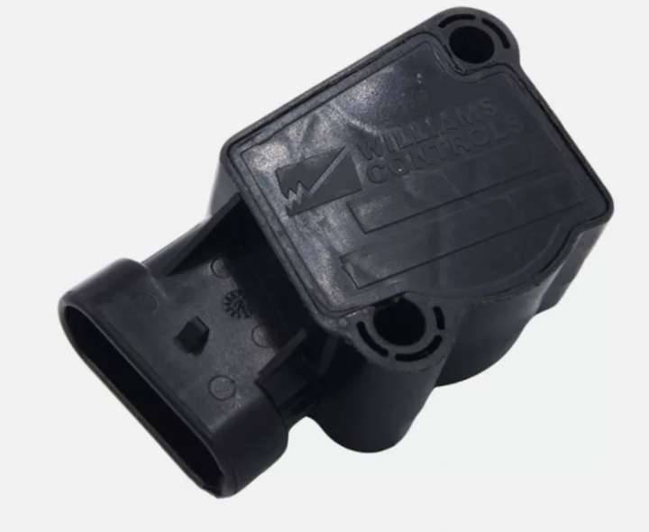
Williams Controls Throttle Position Sensor
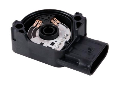
A Williams Controls Throttle Position Sensor is a critical component in commercial vehicles that monitors the engine’s throttle valve position, providing real-time data to the engine control unit (ECU). This information is used by the ECU to precisely adjust fuel injection, ignition timing, and other engine variables, ensuring optimal performance, fuel efficiency, and emissions control.
Product Description & Technical Specifications
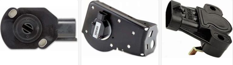
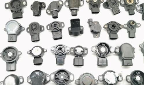
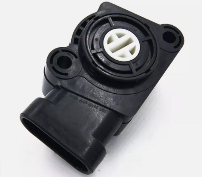
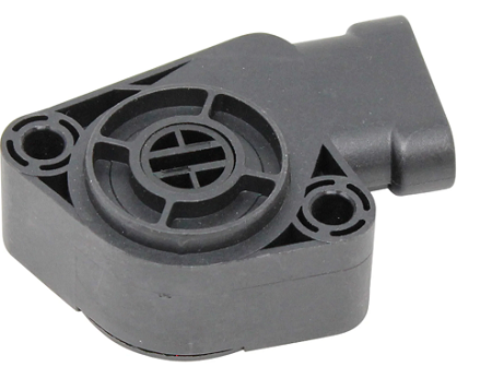
Williams Controls Throttle Position Sensors (TPS) are high-precision position feedback devices engineered for commercial vehicles and heavy equipment. The complete product line includes over 50 models, with 20 popular variants widely used across various industries. These sensors accurately monitor throttle valve position and convert it to a linear voltage signal, providing critical input to the Engine Control Unit (ECU).
Key Features Across Product Line
- Wide temperature range: -40°C to +125°C (with +150°C transient tolerance)
- High vibration resistance: stable output across 10-2000Hz frequency range
- IP67 protection rating , fully dust-tight and water-resistant
- Service life exceeding 5 million cycles for all current production models
- Variety of voltage options (5V, 8V, 12V) and connector configurations
Popular Williams Controls Models
- WCS-132143
- WCS-134030
- WCS-134168
- WCS-133525
- WCS-131973
- WCS-134734
- WCS-133768
- WCS-133248
- WCS-132484w1l
Williams Controls Part Numbers Explained
Williams Controls TPS Model :
134000 Series (Dual-Redundant Heavy-Duty)
- 134143 – Standard dual-redundant TPS (most common variant)
- 134030 – Alternative mounting configuration
- 134734 – Enhanced vibration resistance variant
- 134168 – TPS kit for Cummins engines,see details product wcs-134168
- 134811W1L – TPS for Caterpillar engines
133000 Series (General Heavy-Duty)
- 133313 – Common TPS for International/Navistar see details 133313 TPS
- 133284 – Popular TPS for Volvo/Cummins
- 133693 – Additional variant
- 133904 – Listed in cross-reference
132000 Series (Special Applications)
- 132431W1L – TPS with specific connector
- 132484W1L – 8V TPS for Caterpillar
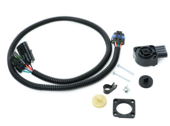
- 132035W1L – Sensor kit with harness
131000 Series (Remote Mount/Alternative)
- 131973 – Major cross-reference TPS (used by multiple OEMs)
- 131040 -TPS Kit
- 131490 – TPS kit
- 131032/WM-531 – Remote mount variants
- 131469 – Listed in catalog
340000 Series (Supersession)
- 340000 – Replaces 133313 in newer applications
WM Series (Non-Contact/Advanced)
- WM-830 – Non-contact Hall-effect position sensor
- WM-526 – Electronic floor pedal assembly
- WM-498-D – Aviation component (not TPS)

WCS-133284 Williams Controls Throttle Position Sensor Wiring
How to do the wiring Williams Control throttle position sensor? Take WCS-133284 as an example, it will have a unique connector, the users just need to plug in the connector as per the bellowing diagram to the end attached to the vehicle. Williams Controls Throttle Position Sensor Wiring Diagram:
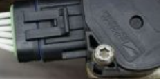
Here is the real picture where the Williams Control Throttle Position Sensor is installed onto a Cummins engine.
Wiring Diagram By Models
WCS-133284 Wiring Diagram (5V)
6-Pin Connector Pin Configuration
- Pin A : APSOUT
- Pin B : APSGND
- Pin C : APSVCC
- Pin D : IVS2NO
- Pin E : IVS1NC
- Pin F : IVSCOM
WCS-132736 Wiring Diagram (12V)
4-Pin Connector Pin Configuration
- Pin 1 (Red): 12V Power Supply
- Pin 2 (Black): Signal Ground
- Pin 3 (White): Throttle Position Signal
- Pin 4 (Green): Shield Ground
Wiring Notes by Model Series
- 5V Models (Most Common) : Includes WCS-133284, WCS-131973, WCS-134143, WCS-134030, WCS-132035, WCS-134734, WCS-133768, WCS-134118A02097, WCS-134460, WCS-131040. These models require a stable 5V DC power supply and typically use 6-pin connectors.
- 8V Models: Includes WCS-132484. Designed for specific Caterpillar applications requiring 8V power input. Note that these models are not interchangeable with 5V variants without voltage regulation.
- 12V Models: Includes WCS-132736, WCS-132739, WCS-131138, WCS-134030W1L. Used in agricultural and off-road equipment. These models feature built-in voltage regulation for harsh environment operation.
Williams Controls Throttle Position Sensor Calibration
It is important to know How to calibrate the throttle position sensor when a Throttle Position Sensor Error. Calibrating your throttle position sensor is a relatively easy process that can be done at home or workshop. Here are several simple steps to calibrate your car’s throttle position sensor (TPS):
- Start the Car, But Don’t Drive: Turn the key to the ‘On’ position so the car’s lights and electronics come on, but don’t start the engine. Make sure your foot isn’t on the gas pedal, and wait for three seconds.
- Tap Dance on the Gas: Press the gas pedal all the way down and let it go back up five times in just five seconds.
- Pause for a Moment: After you’ve done the gas pedal dance, wait for 10 seconds before you do anything else.
- Watch for the Light: Keep an eye on the Check Engine Light. Wait until it stays on and stops blinking for about 20 seconds.
- Lift Your Foot and Start the Engine: Once the Check Engine Light is steady, take your foot off the gas pedal within three seconds, then start the car.
- Let It Idle and Test: Let the car sit and idle for 20 seconds. To make sure everything’s good, rev the engine a couple of times. This checks if the timing and idle speed are just right.
The above process ensures Williams Controls throttle position sensor testing is in good condition, and avoids unnecessary repairs at the roadside.
FAQ
williams controls 131973
What are the key differences between Williams Controls WCS-133284 and WCS-131973?
While both are 5V heavy-duty TPS sensors with IP67 protection and 0.5V–4.5V output, their core differences lie in vehicle fitment and mechanical design:
WCS-133284: Optimized for Cummins ISX/ISM/QSM11 engines (Navistar/Ford/Volvo with Cummins powertrains), 6-pin AMP connector, 5 million-cycle lifespan.
WCS-131973: Designed for International ProStar/Volvo VNL/Peterbilt 579 (Navistar-sourced powertrains), improved vibration resistance (10–2500Hz vs. 10–2000Hz), and direct replacement for Navistar 2603893C91.
Electrical interchangeability: Yes (same pinout and signal protocol), but mechanical mounting brackets may differ—verify vehicle model before substitution.
What tools are required to install and calibrate TPS sensors like 8C40-9F832-BA or WCS-132736?
Installation tools:
Torque wrench (to meet 7–7.5 N·m mounting spec)
Electrical contact cleaner (for connector maintenance)
Wire crimpers/strippers (only if harness modification is needed for pre-2018 vehicles).
Calibration tools:
OEM-specific software (Ford IDS for 8C40-9F832-BA, Navistar ServiceMaxx for N8894090, Cummins INSITE for WCS-133284).
RP1210A-compatible diagnostic adapter (to connect software to the vehicle’s ECU).
Digital multimeter (to verify 5V supply and signal output before/after calibration).
Are these TPS sensors compatible with both 12V and 24V vehicle electrical systems?
All listed TPS models (WCS-133284, N8894090, 8C40-9F832-BA, etc.) are 5V DC regulated sensors, meaning they:
Accept 12V or 24V input from the vehicle’s electrical system (via the ECU’s internal voltage regulator).
Require a stable 5V supply (4.8–5.2V) to function—no external voltage converters are needed.
Critical note: Ensure the vehicle’s ECU can provide the required 5V output (standard for heavy-duty trucks post-2010).