Understanding How Does an Optical Dissolved Oxygen Sensor Work is necessary for modern water quality monitoring. Unlike traditional electrochemical methods, this technology uses luminescence quenching to measure oxygen without consuming it, offering drift-free and maintenance-free accuracy for industrial and environmental applications.
Core Physics of Optical Dissolved Oxygen Sensor: Luminescence Quenching and Stern-Volmer Relationship
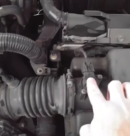
At the heart of every optical dissolved oxygen sensor is a sensing foil or sol-gel matrix containing a luminescent dye, typically a ruthenium complex or platinum porphyrin compound. The working principle involves three sequential events.
Excitation and Luminescence
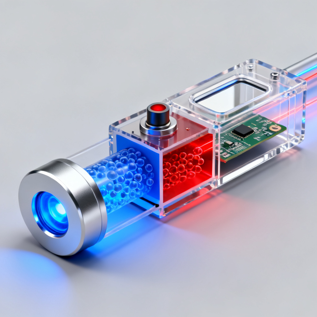
A blue LED (470 nm) pulses to excite the dye molecules. When the dye absorbs this blue light, electrons jump to a higher energy level. As they return to ground state, they emit red light (600-660 nm), a phenomenon called photoluminescence.
Oxygen as a Quencher
Oxygen molecules (O₂) are paramagnetic and accept energy from excited dye molecules. When oxygen collides with the excited dye, it absorbs the energy that would otherwise be released as red light. This dynamic quenching process means more oxygen results in fewer emitted red photons.
The Stern-Volmer Equation
The relationship between oxygen concentration and luminescence intensity or lifetime is defined by the Stern-Volmer equation: I₀/I = 1 + KSV[O₂]. Here, I₀ is luminescence intensity without oxygen, I is intensity with oxygen, KSV is the quenching constant, and [O₂] is oxygen concentration. Lifetime-based measurement is preferred because it resists dye degradation, fouling, and LED intensity fluctuations. The sensor measures how long red light persists after the blue LED turns off; higher oxygen concentration leads to shorter decay time.
Sensor Architecture of Optical Dissolved Oxygen Sensor: From Optode to Signal
An optical dissolved oxygen sensor is a sophisticated assembly of optics, electronics, and protective membranes. Here is the complete hardware breakdown.
The Sensing Element (Optode)
The optode uses a thin layer of oxygen-sensitive dye immobilized in a hydrophobic polymer matrix like silicone or sol-gel. A black opaque layer blocks ambient light and prevents excitation light leakage. A gas-permeable, waterproof membrane (PTFE or silicone) covers the optode, allowing oxygen passage while blocking liquid water, ions, and fouling agents.
The Optical Engine (LEDs and Photodiode)
A high-intensity blue LED serves as the excitation source, with some advanced sensors using a reference LED (red or green) for internal calibration. A silicon photodiode or photomultiplier tube detects red luminescence, with a long-pass optical filter blocking scattered blue light while passing the red signal.
The Role of the PCB in Optical Dissolved Oxygen Sensor
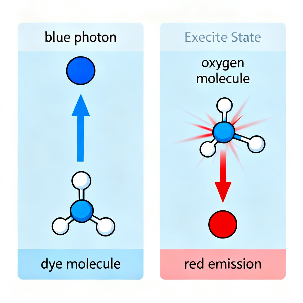
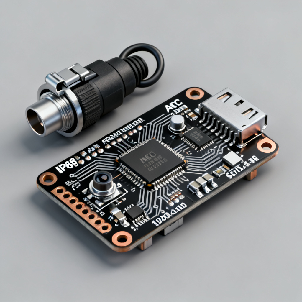
The PCB is the brain of the optical dissolved oxygen sensor. The microcontroller (MCU) runs the Stern-Volmer algorithm, controls LED pulsing, and manages temperature compensation. The analog front-end (AFE) amplifies tiny photodiode current (nanoampere range) and converts it to stable voltage. A high-resolution ADC (16-bit to 24-bit) samples the decay curve of the luminescence signal. A precision RTD (Pt100 or Pt1000) on the PCB near the optode provides real-time temperature compensation, as temperature significantly affects the Stern-Volmer constant. The communication interface outputs the final DO value via RS-485 (Modbus RTU), 4-20 mA analog loop, or digital I²C/SPI.
The Signal Processing Algorithm
The algorithm pulses the blue LED for a few microseconds, waits for it to turn off, measures the decay curve of red luminescence over time, calculates the time constant (τ) of the exponential decay, applies the Stern-Volmer equation using measured τ and temperature-corrected calibration coefficients, and outputs the DO value in mg/L, % saturation, or partial pressure (hPa).
Advanced Features of Optical Dissolved Oxygen Sensor: Drift Compensation and Self-Calibration
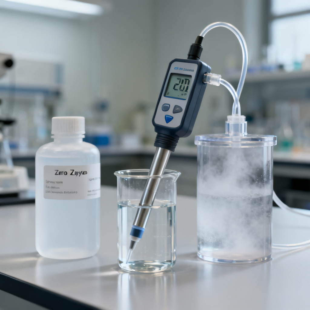
One major advantage of optical dissolved oxygen sensor technology is long-term stability, though dye can degrade over years. To combat this, some sensors include a second LED (green) that excites a non-quenchable reference dye, with the ratio of two signals canceling out drift. Users perform two-point calibration using sodium sulfite solution for zero point and water-saturated air for saturation, storing coefficients in non-volatile memory on the PCB.
Temperature and Pressure Compensation
Oxygen solubility decreases as temperature increases, so the PCB uses the Stern-Volmer temperature coefficient to adjust raw measurement, achieving typical accuracy of ±0.1 mg/L over 0-50°C. Most sensors include a barometric pressure sensor, with % saturation values automatically corrected to local atmospheric pressure. For mg/L readings, pressure compensation is critical at high altitudes.
Response Time and Flow Dependence
The T90 response time is typically 30 to 60 seconds, slower than a Clark cell but sufficient for most applications. Unlike electrochemical sensors, optical dissolved oxygen sensor technology does not consume oxygen, so no minimum flow rate is required. These sensors measure accurately in stagnant water, making them ideal for BOD bottles or deep lakes.
Fouling Resistance and Cleaning
Some optodes are coated with hydrophilic or biocidal layers to prevent biofilm growth. In wastewater applications, a mechanical wiper periodically cleans the membrane. The blue LED is typically rated for 100,000+ hours of operation, with the PCB managing duty cycle to extend lifespan.
Comparison: Optical Dissolved Oxygen Sensor vs Electrochemical (Clark) Sensor
| Feature | Optical Dissolved Oxygen Sensor | Clark Cell (Electrochemical) |
|---|---|---|
| Measurement Principle | Luminescence quenching | Electrochemical reduction |
| Oxygen Consumption | None | Consumes oxygen |
| Flow Dependence | No | Yes (requires >5 cm/s flow) |
| Drift | Very low (<1% per year) | High (electrolyte depletion) |
| Calibration Frequency | Every 6-12 months | Weekly or before each use |
| Warm-Up Time | Instant | 10-30 minutes |
| Interference | None from H₂S, CO₂, or Cl₂ | H₂S poisons the electrode |
| Maintenance | Replace optode every 1-2 years | Replace membrane and electrolyte monthly |
Why optical dissolved oxygen sensor technology wins: no warm-up time, no need to stir the sample, no poisoning from hydrogen sulfide (critical for biogas and wastewater), and long-term deployment without drift.
Applications and PCB Customization for Optical Dissolved Oxygen Sensor OEMs
As a B2B PCB manufacturer, you can offer customized PCBs for optical dissolved oxygen sensor OEMs. Here are specific requirements.
Key PCB Specifications for Optical Dissolved Oxygen Sensor
- Layer Count: 4-layer PCB typical (signal, ground, power, dedicated analog layer).
- Material: High-Tg FR4 or Rogers for low signal loss; analog front-end requires clean ground plane.
- Noise Isolation: High-current LED driver physically separated from sensitive photodiode amplifier; guard rings and shielding vias critical.
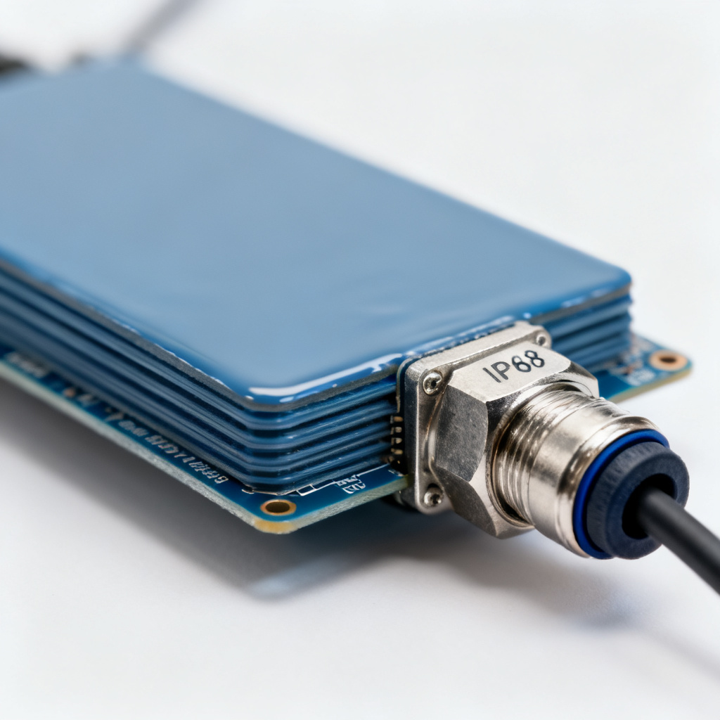
- Connectors: Waterproof IP68-rated connectors (SubConn or Binder) for sensor cable.
- Coating: Conformal coating (acrylic or parylene) to protect against condensation and humidity.
Common Application Profiles for Optical Dissolved Oxygen Sensor
- Aquaculture: Requires sensors with 4-20 mA output for PLC integration; PCB must support 24V DC power and low power consumption for remote buoys.
- Wastewater Treatment: Needs sensors with wiper motor driver circuit on PCB; communication via Modbus RTU over RS-485.
- BOD Testing: Requires sensor with small footprint (12 mm diameter) and fast response time (<30 seconds); PCB must fit inside standard BOD bottle.
- Deep-Sea Oceanography: Requires sensor rated to 6000 meters depth; PCB must be potted in epoxy and use ceramic capacitors to withstand extreme pressure.