Dissolved Oxygen Monitoring for RAS – Protecting Biofilters & Ensuring System Stability
Dissolved oxygen monitoring for RAS is the single most critical measurement layer in recirculating aquaculture. When a system holds thousands of fish in a closed loop, every milligram of oxygen consumed—by gills or by nitrifying bacteria—must be replenished with precision, or the entire biofilter can collapse within hours.
Critical Role of DO in RAS Biofilters
Dissolved oxygen monitoring for RAS must begin where oxygen demand is highest: the biofilter. The biofilter is the biological heart of any RAS, housing dense populations of nitrifying bacteria that convert toxic ammonia into nitrate. This two-stage nitrification process consumes approximately 4.57 mg of oxygen for every milligram of ammonia‑nitrogen oxidized.
When DO concentrations fall below 4 mg/L in the biofilter, nitrification efficiency declines measurably. Below 2 mg/L, the process can slow dramatically—risking ammonia and nitrite accumulation that can kill stock within hours. This is why dissolved oxygen monitoring for RAS must treat the biofilter as the primary monitoring point, not an afterthought. For a complete treatment of nitrification dynamics, see our Pillar Page on RAS DO monitoring technical specifications.
Biofiltration: Why Oxygen Demand Is So High
Biofiltration in a recirculating aquaculture system demands continuous and precise dissolved oxygen monitoring. In a moving bed biofilm reactor (MBBR) or similar biofilter, the microbial community requires a stable aerobic environment to oxidize ammonia efficiently. Research has demonstrated that aeration efficiency—specifically bubble size and oxygen transfer rate—directly determines both biofilm thickness and ammonia removal performance. When dissolved oxygen monitoring for RAS detects a decline in biofilter oxygen levels, it often signals an organic overload or flow imbalance that must be corrected before nitrification is compromised.
Sensor Placement for Biofilter Protection
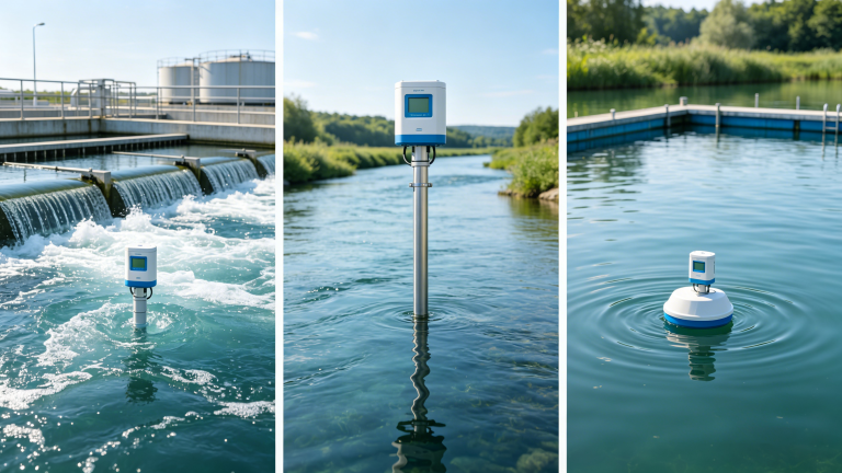
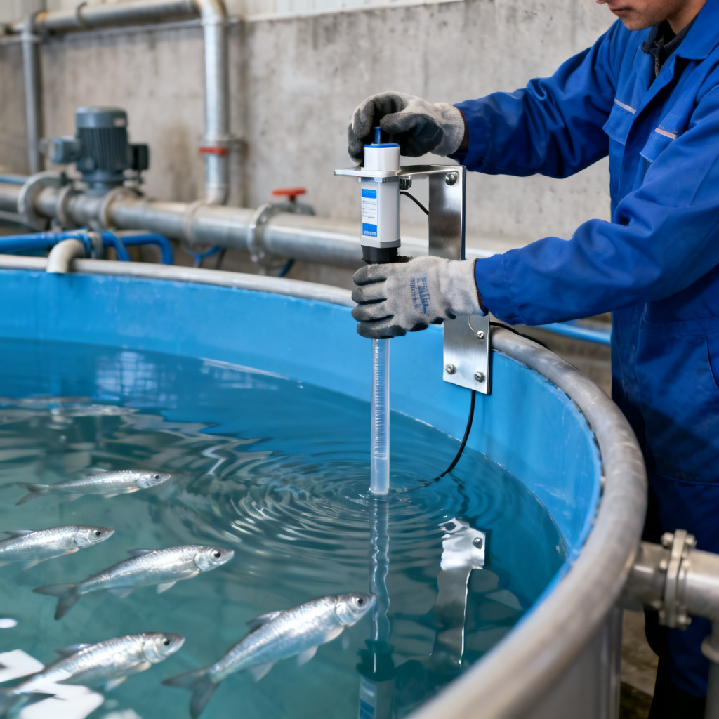
Strategic sensor placement is essential for effective dissolved oxygen monitoring for RAS. A dissolved oxygen sensor installed near an aeration outlet may report artificially high readings that mask dangerous conditions elsewhere in the system. Sensors should be positioned where water is well mixed and representative of true system conditions. In practice, this means monitoring DO at both the biofilter inlet (to measure oxygen available for nitrification) and outlet (to verify consumption rates), while cross‑referencing against the tank where fish reside.
Sensor Selection for RAS Applications
Selecting the right sensor technology for dissolved oxygen monitoring for RAS is a decision that affects maintenance burden, data reliability, and total cost of ownership. Two fundamental technologies compete in this space: optical (luminescence quenching) and electrochemical. Understanding their operational differences is essential for informed specification.
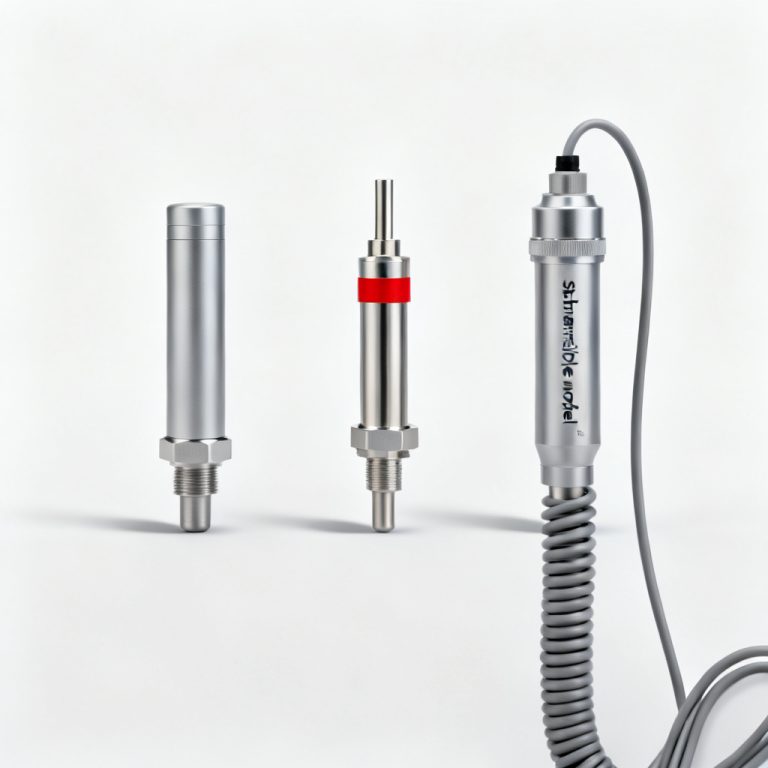
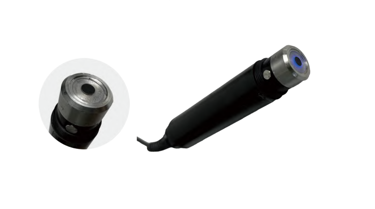
Optical DO Sensors: The Modern Standard for RAS
Optical dissolved oxygen monitoring for RAS relies on fluorescence quenching—a technique that uses a blue LED to excite a luminophore‑coated sensing cap while oxygen molecules quench the emitted light. This method, specified by ISO 17289:2014 and ASTM D888‑05, delivers several decisive advantages for RAS environments:
- No oxygen consumption during measurement—eliminates the minimum flow velocity requirement that plagues electrochemical sensors, enabling accurate readings even in stagnant or near‑zero‑flow zones.
- No electrolyte replacement and no membrane fouling issues—sensor caps last 1–3 years, with calibration stability extending to quarterly or semi‑annual intervals.
- Insensitivity to interfering gases such as H₂S and chlorine, which can poison electrochemical sensor cathodes within days.
These advantages make optical sensors the preferred choice for 24/7 in‑line dissolved oxygen monitoring for RAS, particularly in facilities where access for maintenance is limited. Our optical DO sensor technical comparison provides a detailed side‑by‑side analysis of optical versus electrochemical technologies.
Electrochemical Sensors: When Legacy Technology Still Fits
Electrochemical dissolved oxygen monitoring for RAS, while lower in upfront cost, presents significant operational limitations: membrane fouling in high‑solids water, electrolyte depletion, and a minimum flow velocity requirement that restricts deployment locations. However, for smaller facilities with dedicated maintenance staff and lower stocking densities, electrochemical sensors remain a viable entry point—provided that calibration protocols are rigorously followed.
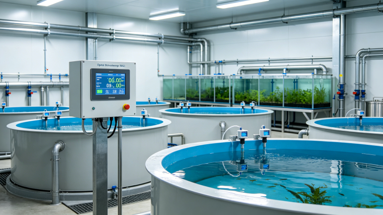
Integration Architecture for RAS
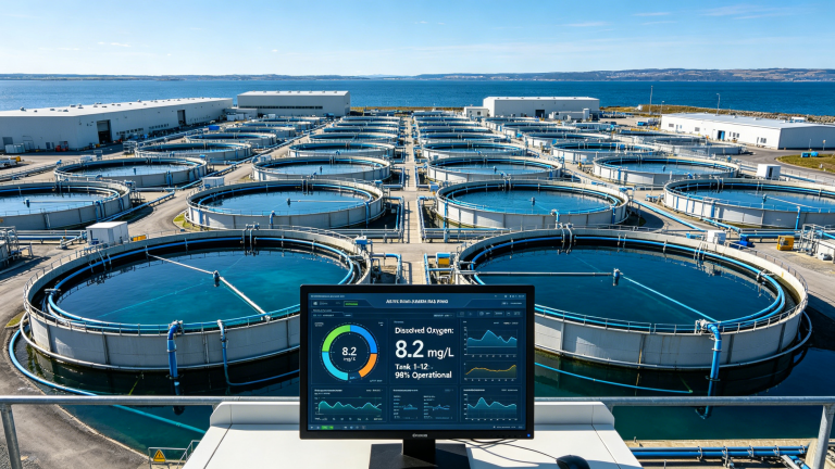
Dissolved oxygen monitoring for RAS realizes its full potential only when integrated into a closed‑loop automation architecture. The standard chain—sensor → transmitter → PLC → actuator—enables real‑time oxygen delivery that matches biological demand with minimal latency. A robust SCADA integration framework is the backbone for this automation, allowing operators to visualize trends, set thresholds, and respond to alarms.
Modbus RTU and PLC Connectivity
Modern dissolved oxygen monitoring for RAS requires industrial‑grade digital communication. Optical DO sensors equipped with RS‑485 interfaces and Modbus RTU protocol enable plug‑and‑play connectivity with PLCs, SCADA systems, and IoT transmitters. This digital backbone supports multi‑drop networking across dozens of sensors without signal loss, slashing installation costs while providing rich data diagnostics for predictive maintenance.
For facilities with existing industrial Ethernet backbones, Profibus and Ethernet/IP provide higher data throughput. Dual‑output sensors that simultaneously support Modbus RTU and 4–20 mA analog signals offer maximum deployment flexibility. For detailed guidance on control system integration, refer to our SCADA integration guide for DO sensors.
Cloud Connectivity and Remote Monitoring
Integrating dissolved oxygen monitoring for RAS with cloud platforms and IoT telemetry enables remote oversight of multiple farms from a central operations center. Historical trend analysis supports long‑term oxygenation optimization, while mobile alerts allow rapid response to alarm conditions even when key personnel are off‑site. Some advanced systems now incorporate quality control charts of daily mortality counts alongside DO and CO₂ forecasting based on sensor data time series, enabling knowledge‑based decision making in precision fish farming.
Redundancy and Fail‑Safe Design
In dissolved oxygen monitoring for RAS, single points of failure are unacceptable. Redundancy is crucial for parameters critical to fish health, particularly dissolved oxygen and water temperature. A single sensor malfunction can cascade into system‑wide issues if not caught in time. Effective fail‑safe design rests on four interlocking principles.
Duplicate Sensors and Cross‑Validation
Using duplicate or backup sensors for critical metrics enables cross‑checking of data and ensures accuracy. For high‑density RAS facilities, a “2‑out‑of‑3” voting logic for sensor alarms is recommended to prevent false‑positive emergency shutdowns while still catching genuine oxygen crashes. When two out of three independent sensors agree that DO has fallen below a critical threshold, the system triggers corrective action; a single aberrant reading generates a maintenance alert instead.
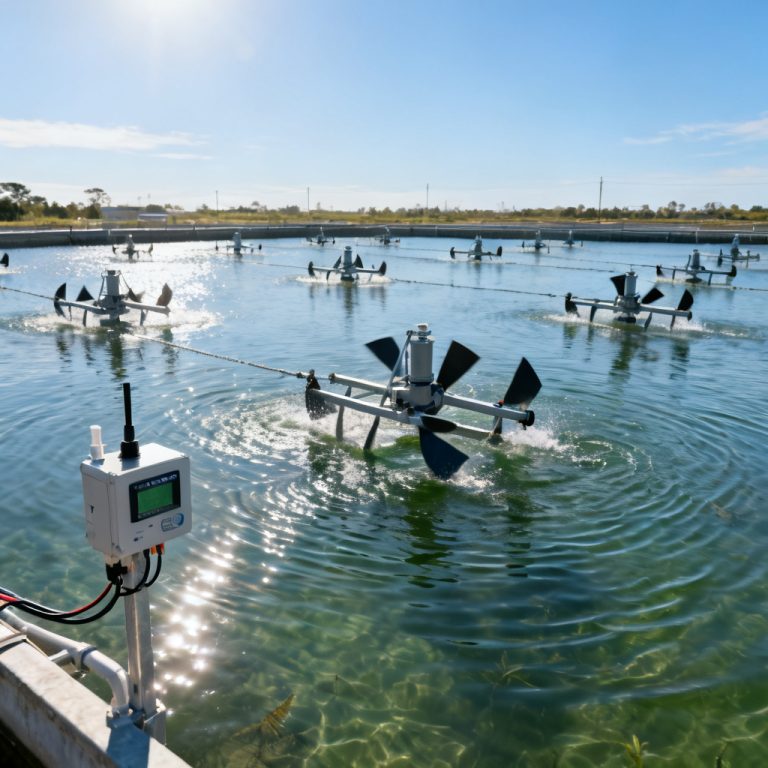
Strategic Sensor Placement and Alarm Configuration
Poor sensor placement will not provide representative water quality data regardless of how many redundant units are installed. Sensors must be positioned strategically away from aeration outlets (which give falsely high readings) and high‑flow areas (which can cause physical damage). Each RAS facility and species has unique requirements; alarm thresholds must be tailored based on species‑specific needs and historical data trends. Generic manufacturer defaults are insufficient—thresholds should be regularly reviewed and adjusted as system conditions evolve.
Power and Connectivity Resilience
Power outages or loss of connectivity can leave a RAS unmonitored, putting fish health at immediate risk. An uninterruptible power supply (UPS), backup generators, and redundant communication methods—such as dual internet and cellular connections—are essential to maintain dissolved oxygen monitoring for RAS during disruptions. Weekly testing of monitoring systems, including battery backup verification and false‑alarm drills, ensures that the system will function correctly when a real emergency occurs.
Case Studies: Land‑Based Salmon and Tropical Species RAS
Land‑Based Atlantic Salmon RAS (Northern Europe)
Large‑scale land‑based Atlantic salmon RAS facilities, with biomasses exceeding 100 kg/m³, represent the most demanding application for dissolved oxygen monitoring. The Norwegian‑Portuguese OPTIRAS project has contributed to improving sensor technology and oxygenation protocols for land‑based farming of Atlantic salmon, with particular focus on automated water quality monitoring systems and alternative oxygenation solutions. Across the industry, published data indicate that oxygen costs can account for 3–5% of total RAS production expenses—making precision oxygen control both a biological necessity and a financial imperative.
Precision Fish Farming in Danish RAS
The Nordic IntelliRAS project has advanced precision fish farming by enabling farmers producing salmonids in RAS to move from experience‑based to knowledge‑based decision making. Researchers collected production data from approximately 15 Danish RAS trout farms, with specific tanks equipped with additional sensors measuring DO, CO₂, and temperature in real time. Forecasting models based on sensor data time series have been developed to predict mortality and guide preventive changes in feeding, demonstrating how dissolved oxygen monitoring for RAS can directly support proactive farm management.
Tropical Species RAS (Southeast Asia)
Tropical RAS facilities producing tilapia, barramundi, and shrimp face distinct dissolved oxygen monitoring challenges. Higher water temperatures reduce oxygen solubility—freshwater saturation at 28°C is approximately 7.8 mg/L at sea level—while elevated metabolic rates increase oxygen demand. These systems typically combine multi‑parameter monitoring (DO, temperature, pH, conductivity, ammonia) on a unified SCADA platform with cellular IoT gateways for remote fleet management. For shrimp, sensors are mounted in the lower third of the water column but above the sludge zone, where benthic species experience the lowest oxygen availability. Our IoT solutions for aquaculture monitoring provides further information on remote fleet management architectures.
Frequently Asked Questions
Why is dissolved oxygen monitoring for RAS more demanding than for pond or cage aquaculture?
Dissolved oxygen monitoring for RAS must account for the fact that every milligram of waste and every gram of oxygen consumed stays in the system until actively removed or replenished. Unlike ponds (where nature provides buffering) or cages (where the ocean dilutes problems), RAS offers no natural reset. Parameters are tightly coupled: a pH drop changes ammonia toxicity, a biofilter oxygen decline slows nitrification, and CO₂ accumulation impairs fish respiration. Continuous, multi‑point DO monitoring is therefore mandatory.
What sensor technology is best for dissolved oxygen monitoring in RAS biofilters?
Optical DO sensors based on ISO 17289:2014 and ASTM D888‑05 are the preferred choice for RAS biofilter monitoring. They consume no oxygen during measurement, require no minimum flow velocity, and maintain calibration stability over months—making them ideal for deployment in biofilter sumps where conditions can be challenging. For a complete technical comparison, see our optical vs electrochemical sensor guide.
How many dissolved oxygen sensors does a typical RAS facility need for adequate redundancy?
For critical monitoring points—biofilter inlet/outlet and each culture tank—a minimum of two independent sensors is recommended, with “2‑out‑of‑3” voting logic applied in high‑density facilities where false alarms could trigger costly emergency shutdowns. Sensor placement must avoid aeration outlets and high‑flow zones that produce unrepresentative readings.