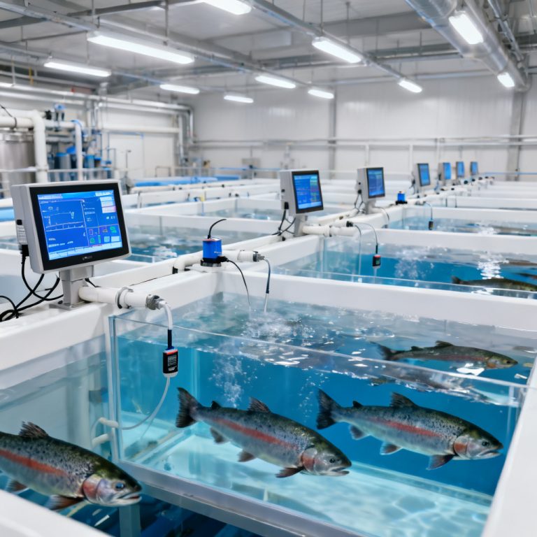
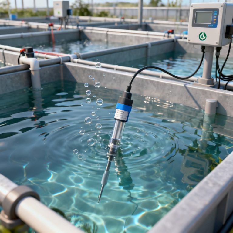
Accurate Optical DO Sensor Calibration is essential for reliable dissolved oxygen measurement in environmental monitoring, wastewater treatment, aquaculture, and industrial process control. Optical DO sensors, based on luminescence quenching technology, offer superior stability and low maintenance compared to traditional Clark-type electrodes. However, even the most advanced optical sensors require periodic calibration to maintain precision and comply with regulatory standards.
This comprehensive guide: “Optical DO Sensor Calibration Step by Step Guide”compiles best practices from leading manufacturers (YSI, Hach, Campbell Scientific, and others) to provide a single, authoritative resource. We cover everything from why calibration matters to step-by-step procedures, common pitfalls, and troubleshooting. Whether you are a field technician, lab manager, or PCB integration engineer, this page will equip you with the knowledge to achieve reliable DO data.
Why Calibrate an Optical DO Sensor?
Optical DO sensor calibration compensates for sensor-to-sensor variability, foil aging, and environmental factors such as temperature, barometric pressure, and salinity. Unlike electrochemical sensors, optical DO sensors do not consume oxygen during measurement, but their sensing foil (luminophore) can degrade over time due to UV exposure, fouling, or chemical attack. Regular calibration ensures:
- Traceability to NIST standards (via saturated air or zero-oxygen solutions)
- Compensation for drift (typically less than 1% per month, but recommended monthly or before critical deployments)
- Cross-compatibility between sensors and data loggers
- Compliance with EPA, ISO, or local water quality regulations
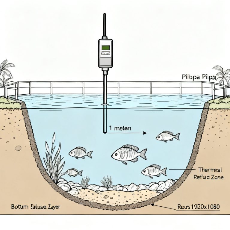
Key note: Always calibrate the sensor at the measurement temperature (±2°C) for best accuracy. If the sensor is used across a wide temperature range, perform a multi-point calibration (e.g., 0°C, 20°C, 35°C) if supported by the manufacturer.
Required Tools and Materials for Optical DO Sensor Calibration
Before starting your Optical DO Sensor Calibration, gather the following:
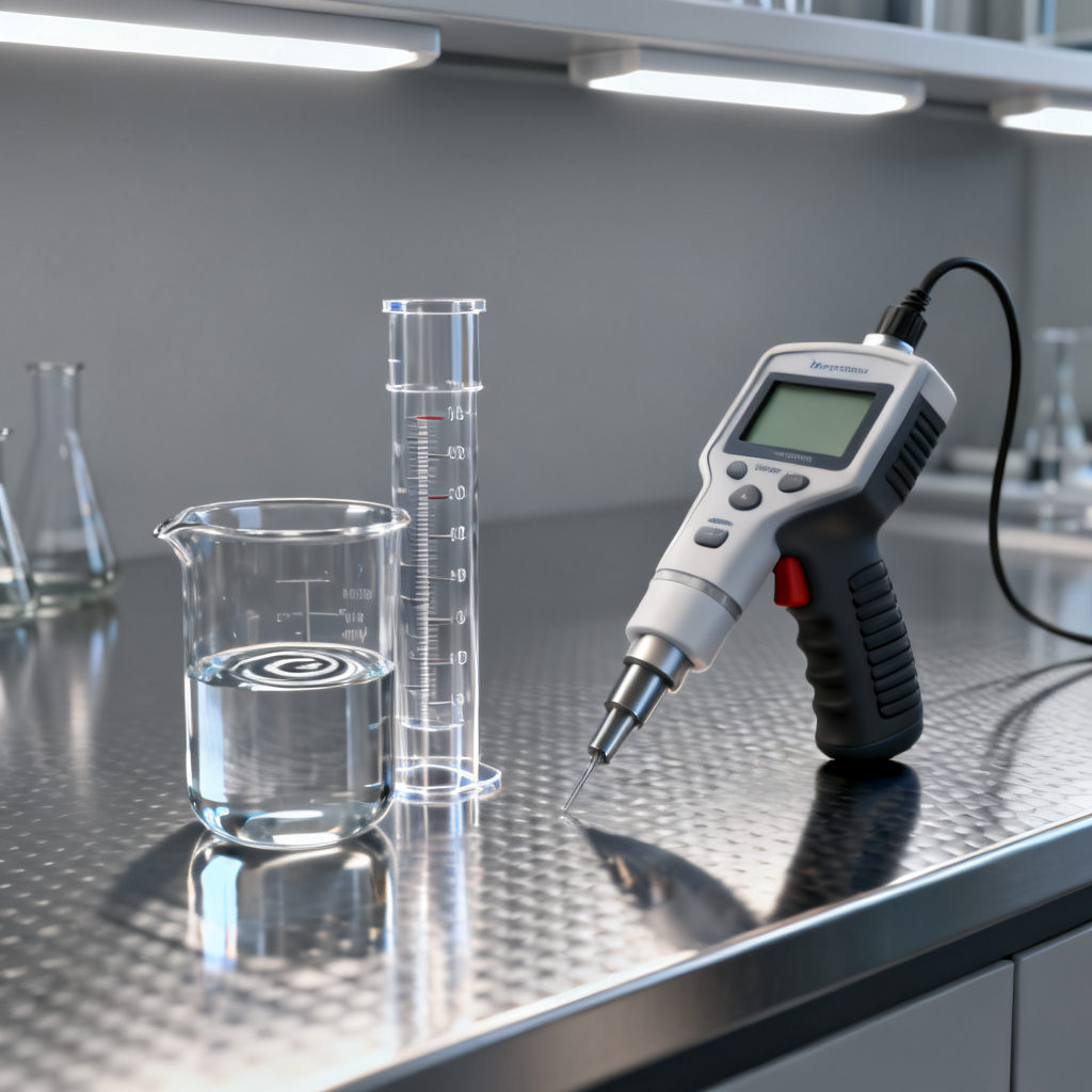
- Calibration vessel (e.g., a BOD bottle, calibration sleeve, or a clean plastic container with a tight lid)
- Distilled or deionized water (for zero-point solution preparation)
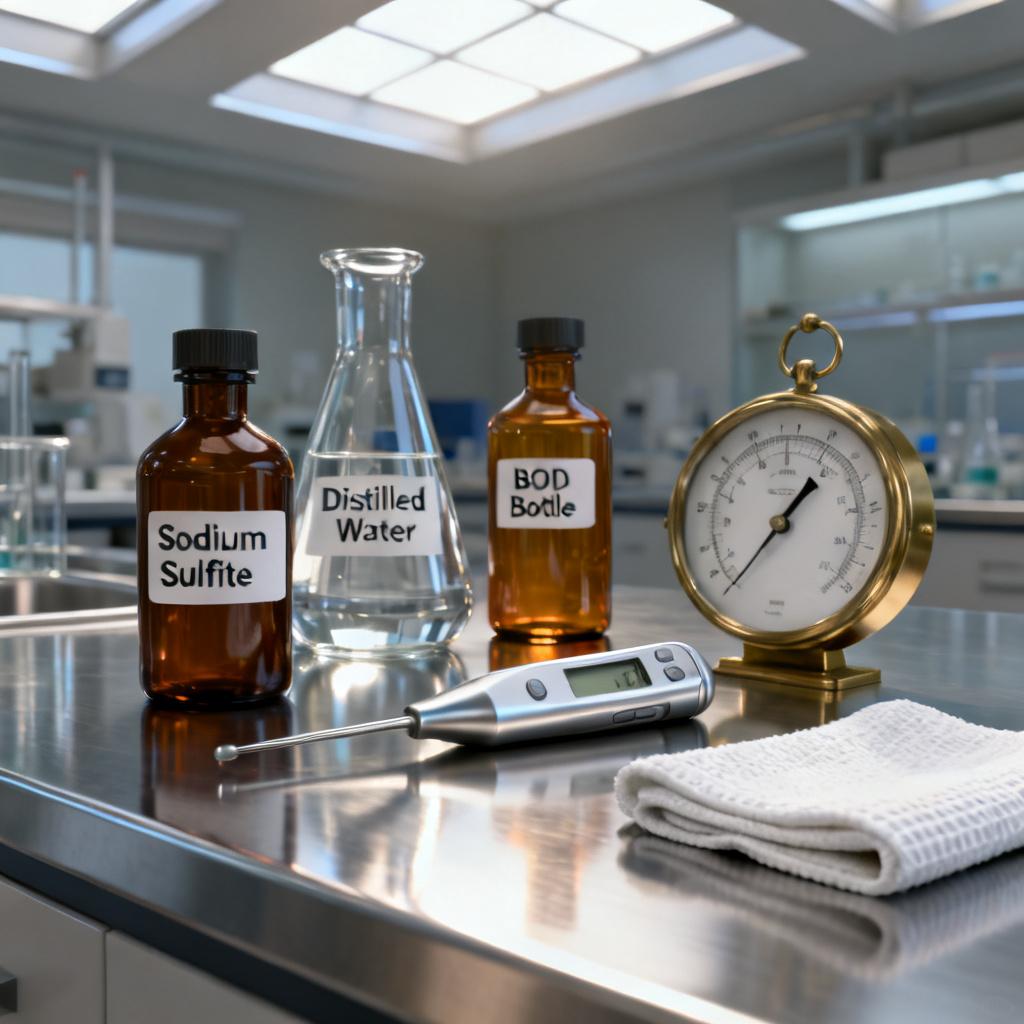
- Sodium sulfite (Na₂SO₃) or commercial zero-oxygen solution (e.g., YSI 3682)
- Barometer (for local atmospheric pressure, if sensor does not auto-compensate)
- Thermometer (accuracy ±0.1°C)
- Clean, lint-free cloth (to wipe the sensor cap)
- Sensor-specific software or display (for entering calibration values)
- Optional: Salinity standard (if calibrating in brackish or seawater)
Step 1: Prepare the Sensor and Environment
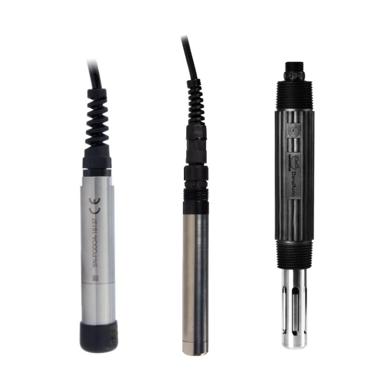
- Inspect the sensor cap: Ensure the sensing foil is clean, free of scratches, and not cracked. Replace if damaged (typical cap life: 1–3 years).
- Warm up the sensor: Connect the sensor to the meter or data logger and allow it to stabilize for 15–30 minutes in air at the calibration temperature. This ensures the internal electronics and optics reach thermal equilibrium.
- Record environmental data: Measure the current barometric pressure (in mmHg or mbar) and water temperature. Most modern optical DO sensors have built-in temperature and pressure sensors, but double-check if using external loggers.
Pro tip: For field calibrations, perform the procedure in a shaded, stable location away from direct sunlight and wind to avoid rapid temperature fluctuations.
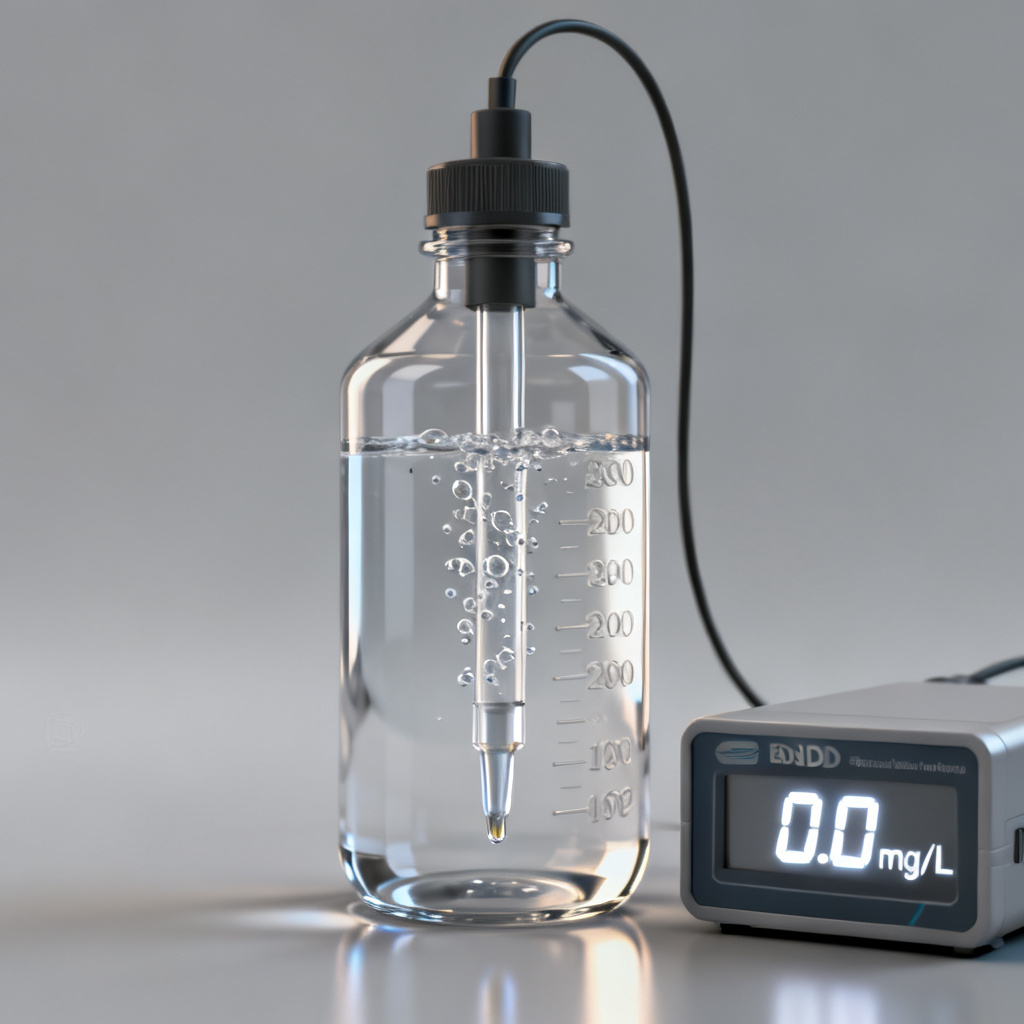
Step 2: Zero‑Point Calibration (0% Saturation)
The zero-point adjustment sets the sensor’s baseline when no oxygen is present. This step is critical for low-level DO measurements (e.g., anoxic zones, bioreactors).
Method A: Sodium Sulfite Solution (Recommended)
- Prepare a zero‑oxygen solution: Add approximately 1 gram of sodium sulfite (Na₂SO₃) and a small crystal of cobalt chloride (CoCl₂·6H₂O) as a catalyst to 100 mL of distilled water. Stir until dissolved. The solution will consume all dissolved oxygen within 2–5 minutes.
- Fill the calibration vessel: Pour the solution into the calibration sleeve or BOD bottle, ensuring no air bubbles remain.
- Immerse the sensor: Submerge the sensor’s sensing tip fully in the solution. Avoid trapping air under the cap.
- Wait for stabilization: Allow 3–10 minutes for the reading to stabilize. A stable reading (change less than 0.01 mg/L over 30 seconds) indicates equilibrium.
- Enter the zero value: On the meter or software, set the calibration point to 0.0 mg/L or 0% saturation. Confirm the sensor accepts the value.
Method B: Commercial Zero‑Oxygen Standard
- Use a pre‑mixed zero‑oxygen solution (e.g., YSI 3682 or Hach ZOB). Follow the same immersion and stabilization steps. This offers greater consistency and avoids chemical residue.
Important: After zero‑point calibration, rinse the sensor thoroughly with distilled water to remove any sodium sulfite residue, as it can foul the foil if left to dry.
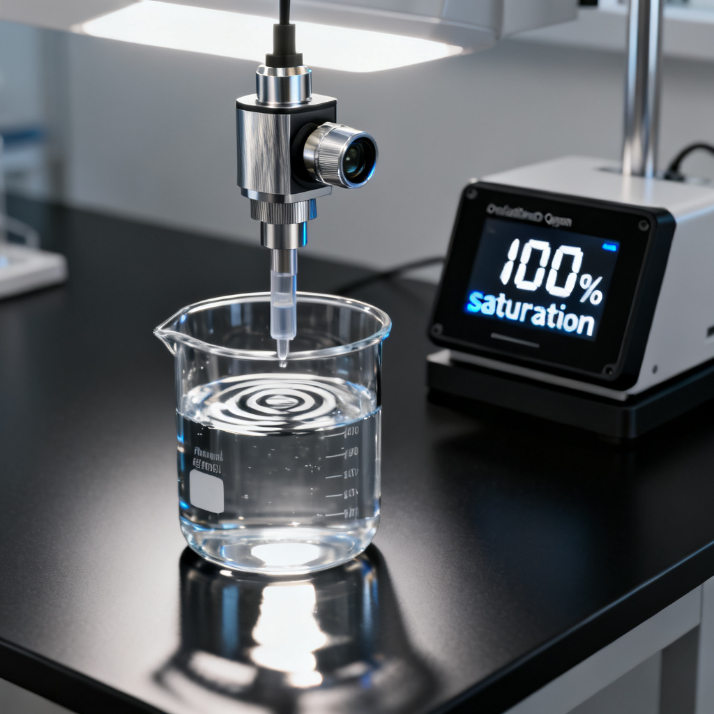
Step 3: Air‑Saturation Calibration (100% Saturation)
This is the most common calibration point for optical DO sensors and is performed in water‑saturated air (100% relative humidity). It sets the sensor’s response to the maximum oxygen concentration at the current barometric pressure and temperature.
Procedure for Air‑Saturation Calibration
- Prepare a water‑saturated environment: Place a small amount of distilled water (1–2 cm depth) in the bottom of the calibration vessel. Do not submerge the sensor—only the water vapor should contact the foil.
- Insert the sensor: Position the sensor cap just above the water surface (not touching the liquid). Seal the vessel with a vented cap (if provided) or leave a small gap for pressure equalization.
- Wait for equilibrium: Allow 5–15 minutes for the air inside the vessel to become fully saturated with water vapor. The sensor reading will stabilize at a value close to 100% saturation.
- Enter the calibration value:
- If the meter auto‑compensates for barometric pressure and temperature, simply set the point to 100% (or the calculated saturation value, e.g., 9.09 mg/L at 20°C, 1 atm).
- If manual entry is required, calculate the expected saturation using a standard DO table or the following formula (valid for freshwater at 1 atm):
DO (mg/L) = 14.652 – 0.41022T + 0.007991T² – 0.000077774T³
where T = temperature in °C. Then multiply by the ratio of actual barometric pressure to standard pressure (760 mmHg).
- Confirm acceptance: The meter should indicate a successful calibration (e.g., “Cal OK” or a slope value near 1.0).
Note: For sensors with built‑in pressure compensation, ensure the barometer is calibrated and the sensor is exposed to ambient air (not enclosed) for at least 10 minutes before starting.
Step 4: Verify Calibration Accuracy
After completing your Optical DO Sensor Calibration, perform a verification check using a known standard or a second independent method.
- Air verification: Remove the sensor from the vessel and hold it in ambient air (away from breath or heat sources). The reading should be within ±2% of the theoretical saturation value based on current barometric pressure and temperature.
- Winkler titration (optional): For highest accuracy, collect a water sample and perform a Winkler titration. Compare the result to the sensor reading. Discrepancies greater than 0.2 mg/L may require recalibration or sensor cap replacement.
- Salinity correction: If measuring in saltwater, ensure the salinity compensation is enabled and the correct value is entered (e.g., 35 ppt for seawater). Calibrate in freshwater or use a salinity‑matched zero‑point solution.
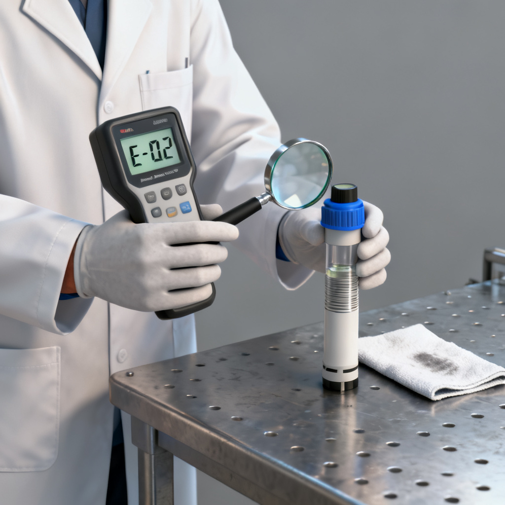
Common Pitfalls and Troubleshooting in Optical DO Sensor Calibration
| Issue | Possible Cause | Solution |
|---|---|---|
| Sensor reads greater than 100% in air | Low barometric pressure (e.g., high altitude) | Enter correct pressure manually; recalibrate at 100% |
| Sensor reads less than 0.0 mg/L in zero solution | Residual oxygen in solution or air bubbles | Stir solution longer; ensure no trapped air |
| Slow stabilization (greater than 15 min) | Fouled or degraded sensor cap | Clean cap with soft cloth; replace if scratched or pitted |
| Calibration slope less than 0.8 or greater than 1.2 | Foil damage or contamination | Replace sensor cap; recalibrate |
| Erratic readings | Electromagnetic interference (EMI) or moisture in connector | Check cable shielding; dry connector with compressed air |
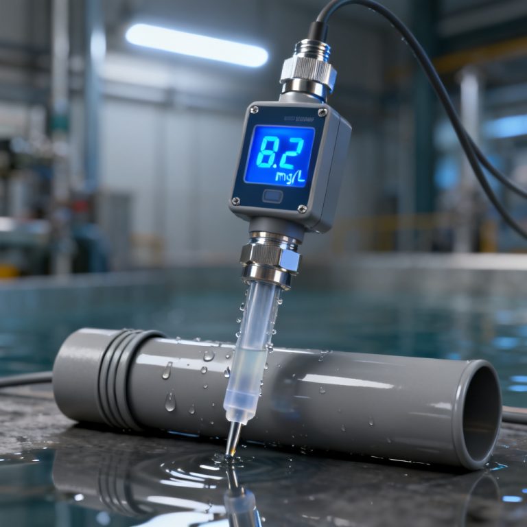
For PCB integration: If the optical DO sensor is connected to your custom data logger or PLC, ensure the analog output (0–5V or 4–20 mA) is scaled correctly. After calibration, the output at 0% should be approximately 0V (or 4 mA) and at 100% should be approximately 5V (or 20 mA). Use a precision resistor to verify.
Best Practices for Long‑Term Accuracy
- Calibrate before each deployment (or at least monthly for continuous monitoring).
- Store the sensor with a protective cap and a damp sponge (to maintain humidity) when not in use. Avoid drying out the foil.
- Replace the sensor cap annually or when calibration slope deviates greater than 10% from nominal.
- Log calibration data (date, time, barometric pressure, temperature, slope, offset) for audit trails.
- Avoid extreme conditions: Do not expose the sensor to temperatures greater than 50°C or direct UV for prolonged periods.
- Use manufacturer‑approved cleaning solutions (e.g., mild soap and water; avoid acetone or alcohol that may attack the foil).
Conclusion
Optical DO sensor calibration is a straightforward but critical process for ensuring data quality. By following this step‑by‑step guide—combining zero‑point and air‑saturation methods with proper environmental compensation—you can achieve ±0.1 mg/L accuracy or better. Regular calibration, combined with proper sensor care, will extend the life of your optical DO sensor and provide reliable measurements for years.
For PCB manufacturers integrating optical DO sensors into custom monitoring systems, we recommend including a calibration mode in your firmware that prompts the user to perform these steps. Additionally, consider adding a barometric pressure sensor and temperature probe to your PCB design to enable automatic compensation—this reduces user error and improves overall system accuracy.
Need custom PCBs for your optical DO sensor project? Contact our engineering team for a free design review and quick‑turn prototype. We specialize in high‑reliability boards for environmental monitoring applications.
Frequently Asked Questions about Optical DO Sensor Calibration
How often should I perform Optical DO Sensor Calibration?
Optical DO Sensor Calibration is recommended before each deployment or at least monthly for continuous monitoring. Calibrating at the measurement temperature ensures accuracy across varying conditions.
What is the difference between zero-point and air-saturation calibration for an optical DO sensor?
Zero-point calibration sets the baseline at 0% saturation using a zero-oxygen solution, while air-saturation calibration sets the maximum response at 100% saturation in water-saturated air. Both steps are essential for a complete Optical DO Sensor Calibration.
Can I calibrate an optical DO sensor without a barometer?
Most modern optical DO sensors have built-in barometric pressure compensation. However, for manual calibration, you need an external barometer to calculate the correct saturation value. Accurate Optical DO Sensor Calibration requires pressure data.
Why does my optical DO sensor reading drift after calibration?
Drift can be caused by a degraded or fouled sensor cap, incorrect temperature compensation, or rapid environmental changes. Regular Optical DO Sensor Calibration and cap replacement (every 1–3 years) minimize drift.
What tools do I need for Optical DO Sensor Calibration?
You need a calibration vessel, distilled water, sodium sulfite or commercial zero-oxygen solution, a barometer, a thermometer, a clean cloth, and sensor-specific software. These tools ensure precise Optical DO Sensor Calibration.
Last updated: [Current Date] | Compliance: ISO 9001:2015 | References: YSI ProDSS Manual, Hach HQd Series User Guide, Campbell Scientific CS511-L Manual